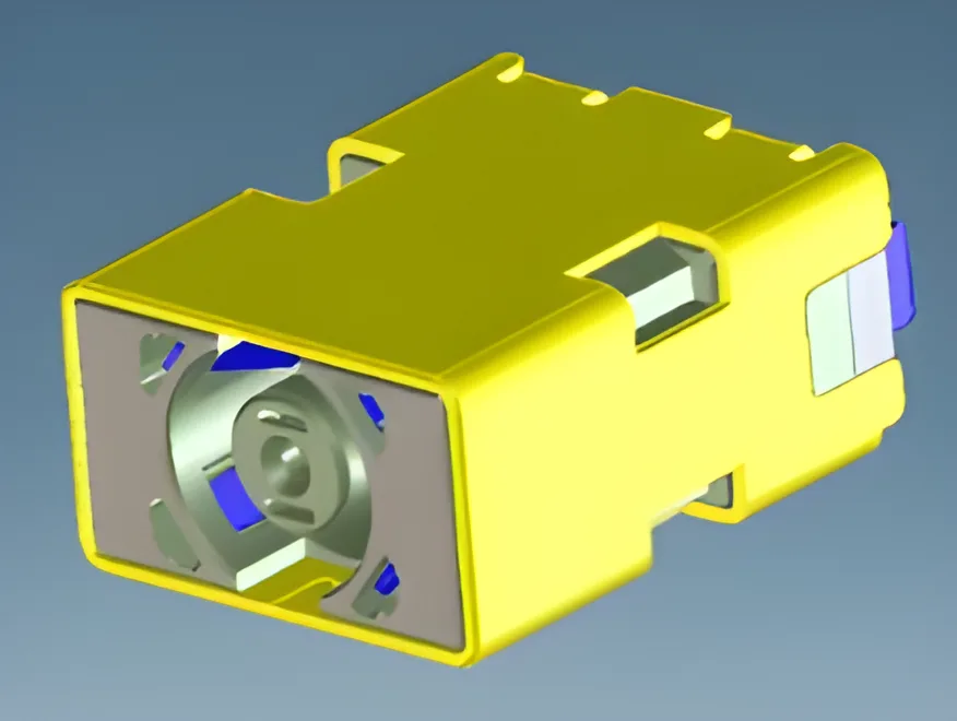
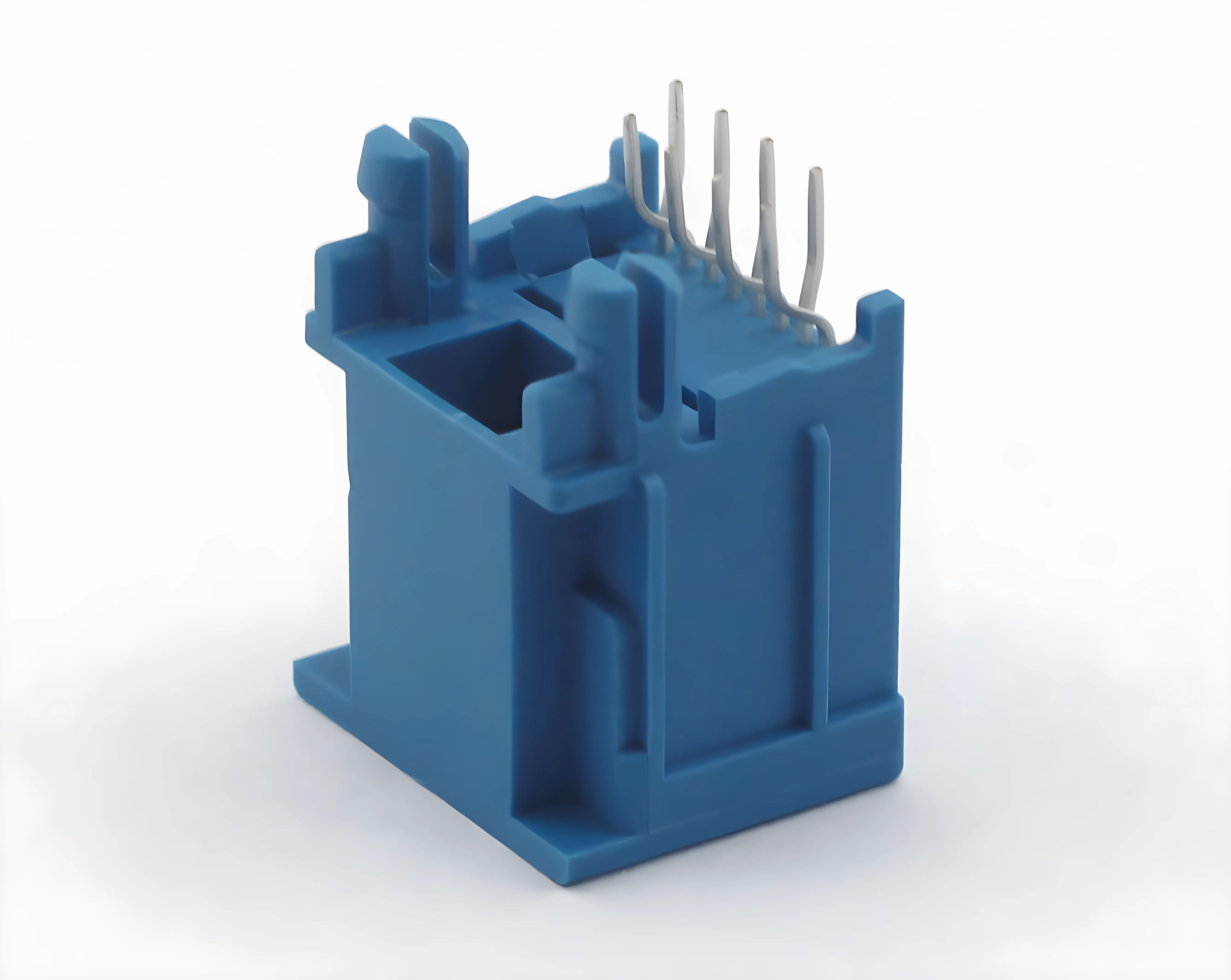
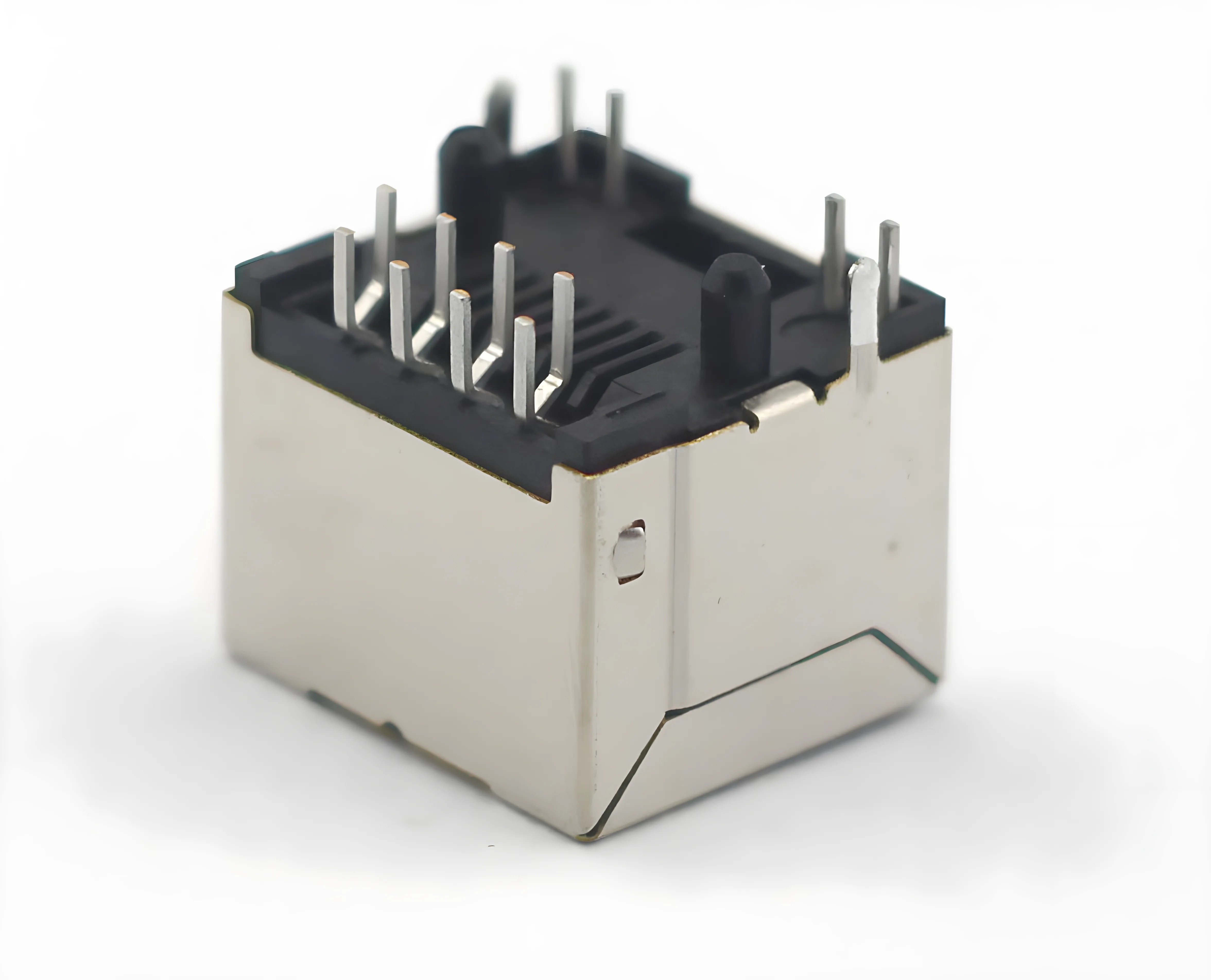
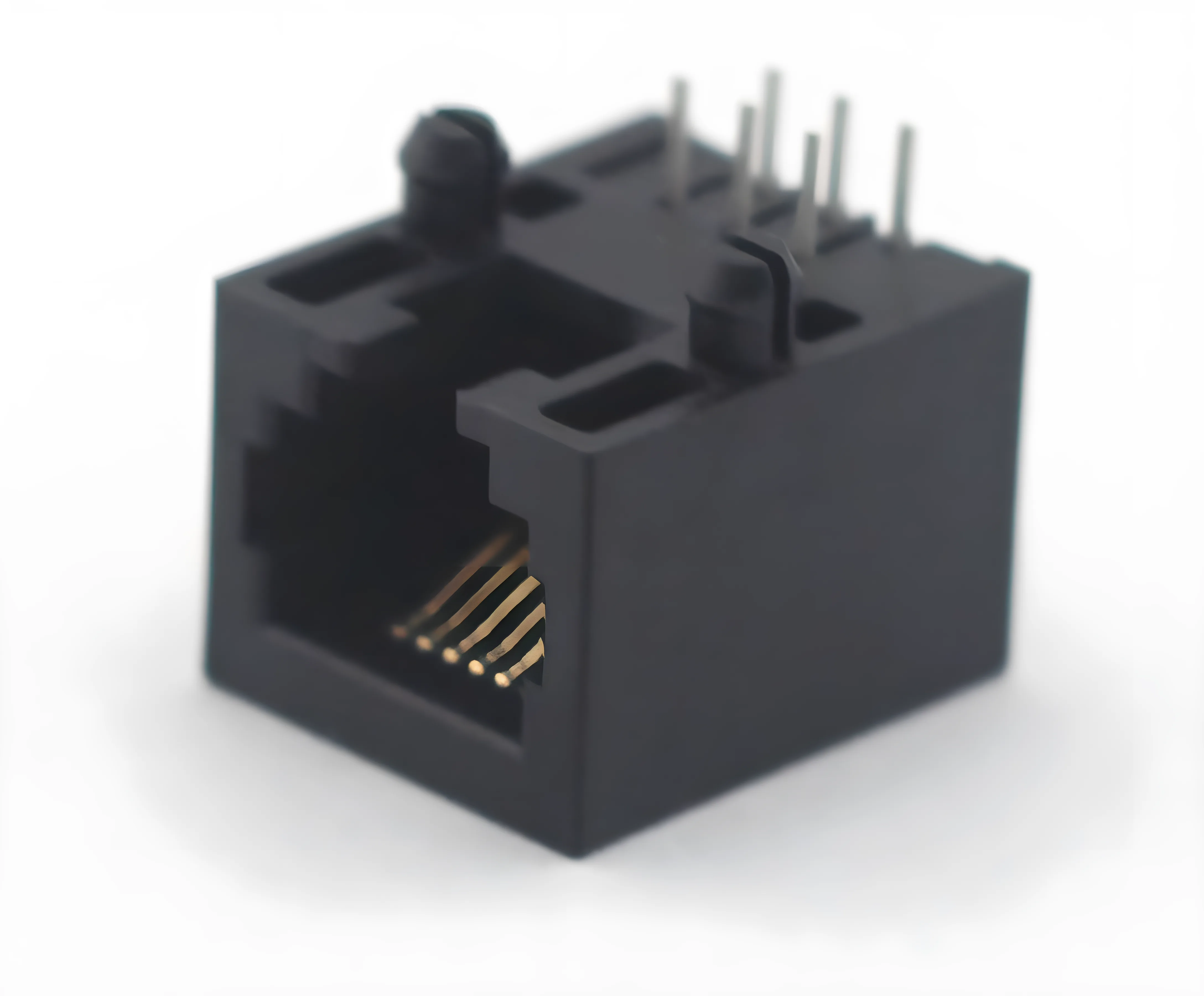
A connector datasheet is the single most important document you will reference when selecting a connector for any design. It contains every electrical, mechanical, and environmental specification you need to determine whether a part will perform reliably in your application. Yet many engineers — especially those early in their careers — skim datasheets or focus on only one or two parameters, missing critical details that surface later as field failures.
Reading a connector datasheet correctly is a skill. It requires understanding what each parameter means, how values are measured, and where manufacturers sometimes leave room for interpretation. A misread current rating or an overlooked temperature derating curve can mean the difference between a product that lasts ten years and one that fails in six months.
This guide walks you through every major section of a typical connector datasheet, explains the parameters that matter most, and highlights the mistakes engineers commonly make. Whether you are evaluating fiber optic connectors or high-current automotive terminals, the principles are the same.
Anatomy of a Connector Datasheet
Before diving into individual parameters, it helps to understand the overall structure. Most connector datasheets from reputable manufacturers follow a similar layout, though the order of sections may vary.
A typical connector datasheet includes the following sections:
- Part number and series overview — identifies the connector family, variant codes, and available configurations.
- Electrical specifications — current rating, voltage rating, contact resistance, insulation resistance, and dielectric withstanding voltage.
- Mechanical specifications — mating cycles, insertion force, extraction force, and retention force.
- Environmental specifications — operating temperature range, IP rating, vibration and shock resistance, salt spray hours.
- Material and plating details — housing material, contact base metal, plating type and thickness.
- Dimensional drawings — outline dimensions, pin pitch, mounting hole patterns, mating interface geometry.
- Compliance and certifications — UL, CE, RoHS, REACH, and any industry-specific approvals.
- Ordering information — part number structure, packaging options, and minimum order quantities.
Some manufacturers combine sections or add application-specific data such as signal integrity parameters for high-speed connectors. Regardless of format, the core information is always present. Your job is to know where to find it and how to interpret it.
Electrical Parameters
Electrical parameters define how a connector handles current, voltage, and signal integrity. These are typically the first specifications engineers check, and for good reason — an electrical failure in a connector can damage downstream components or create a safety hazard.
Current Rating
The current rating tells you the maximum continuous current a single contact can carry under specified conditions. This is one of the most misunderstood parameters on any connector datasheet.
Most manufacturers test current rating at a specific ambient temperature — often 20 degrees C or 25 degrees C — and define the rating as the current that produces a temperature rise of 30 degrees C at the contact. If your application operates at a higher ambient temperature, you must derate the current accordingly. We will cover derating in detail later in this article.
Voltage Rating
Voltage rating specifies the maximum working voltage the connector can safely handle. This value accounts for the insulation properties of the housing material and the spacing between adjacent contacts. Always confirm whether the rating is AC or DC, as some datasheets list both.
Contact Resistance
Contact resistance measures the electrical resistance across a mated contact pair, typically in milliohms. Lower is better. A high contact resistance generates heat under load and can degrade signal quality. Initial values on a new connector are usually very low, but contact resistance can increase over time due to wear, corrosion, or fretting.
Insulation Resistance
Insulation resistance measures the resistance between adjacent contacts or between contacts and the housing. Values are typically in the hundreds of megaohms to gigaohms range. This parameter confirms that current will not leak between circuits through the insulating material.
Dielectric Withstanding Voltage
Also called hi-pot or proof voltage, this is the maximum voltage the connector can withstand for a short duration (usually 60 seconds) without breakdown. It is a safety margin test, not an operating parameter. The dielectric withstanding voltage is always significantly higher than the rated working voltage.
Electrical Parameters: Example Values
The table below shows typical electrical parameter ranges you might encounter on a connector datasheet. Actual values vary by connector type and size.
| Parameter | Typical Range | Unit | Test Condition |
|---|---|---|---|
| Current Rating | 1 – 300 | A | 20°C ambient, 30°C rise |
| Voltage Rating (AC/DC) | 30 – 1000 | V | Sea level |
| Contact Resistance | 0.5 – 20 | mΩ | Initial, at 20 mV open circuit |
| Insulation Resistance | 500 – 5000 | MΩ | 500 V DC applied |
| Dielectric Withstanding Voltage | 500 – 5000 | V AC | 60 seconds, sea level |
Mechanical Parameters
Mechanical parameters describe how the connector behaves physically during mating, unmating, and long-term use. These specifications directly affect assembly ergonomics, maintenance procedures, and connector lifespan.
Mating Cycles
Mating cycles (also called durability) indicate how many times a connector can be mated and unmated while still meeting its electrical and mechanical specifications. A connector rated for 500 mating cycles is designed for applications where it will be connected and disconnected periodically. A connector rated for 10,000 cycles is built for frequent-access applications like test equipment.
Insertion and Extraction Force
Insertion force is the force required to fully mate the connector. Extraction force is the force required to separate it. These values matter for operator ergonomics and for ensuring the connector stays mated under vibration. Too little extraction force and the connector may work loose. Too much insertion force and assembly workers may experience fatigue or fail to fully seat the connector.
Retention Force
Retention force measures how well the connector resists being pulled apart along its mating axis once fully engaged. This is distinct from extraction force, which involves the normal unmating motion. Retention force is critical in applications subject to cable pull or vibration.
Mechanical Parameters: Example Values
| Parameter | Typical Range | Unit | Notes |
|---|---|---|---|
| Mating Cycles | 50 – 10,000 | cycles | Per IEC or EIA test methods |
| Insertion Force (per contact) | 0.5 – 5.0 | N | Maximum, single contact |
| Extraction Force (per contact) | 0.3 – 3.0 | N | Minimum, single contact |
| Retention Force (housing) | 10 – 100 | N | Axial pull on mated pair |
Environmental Parameters
Environmental parameters define the conditions under which the connector will function reliably. These are especially important for connectors used in automotive, industrial, outdoor, and military applications. If you have worked with automotive connector IP ratings, you already know how critical these specs can be.
Operating Temperature Range
The operating temperature range specifies the minimum and maximum temperatures at which the connector will meet all its rated specifications. A standard commercial connector might be rated from -40 degrees C to +105 degrees C. High-temperature variants for engine compartment or industrial oven applications may extend to +150 degrees C or beyond.
IP Rating
The Ingress Protection (IP) rating indicates the connector's resistance to dust and water. An IP67-rated connector is dust-tight and can withstand temporary immersion in water. An IP69K-rated connector can handle high-pressure, high-temperature washdown. Always check whether the IP rating applies to the mated condition, unmated condition, or both.
Vibration and Shock Resistance
Vibration specs define the frequency range, amplitude, and duration the connector can endure without electrical discontinuity. Shock specs define the peak acceleration (in g) and pulse duration. These parameters are tested per standards such as IEC 60512 or MIL-STD-202.
Salt Spray Resistance
Salt spray testing (per ASTM B117 or ISO 9227) evaluates corrosion resistance. The datasheet will list the number of hours the connector can withstand salt spray exposure without functional degradation. This is essential for marine, coastal, and road-vehicle applications.
Environmental Parameters: Example Values
| Parameter | Typical Range | Unit | Test Standard |
|---|---|---|---|
| Operating Temperature | -40 to +125 | °C | Continuous operation |
| IP Rating | IP20 – IP69K | — | IEC 60529 |
| Vibration | 10 – 2000 Hz, up to 15g | Hz / g | IEC 60512-06 |
| Shock | 30 – 100 | g | 11 ms half-sine pulse |
| Salt Spray | 48 – 1000 | hours | ASTM B117 |
Material and Plating Specifications
The materials section of a connector datasheet tells you what the connector is made of — and by extension, how it will perform over time in your specific environment. Two connectors with identical electrical ratings can have very different service lives depending on their materials and plating.
Housing Materials
Connector housings are typically molded from engineering thermoplastics. The datasheet will list the specific resin (such as PA66, PBT, LCP, or PPS) along with its UL flammability rating (usually UL 94 V-0). Glass-filled variants offer higher mechanical strength and temperature resistance. The choice of housing material affects operating temperature limits, chemical resistance, and mechanical durability.
Contact Base Metal
Contacts are usually stamped or machined from copper alloy — most commonly phosphor bronze (C5191) or brass (C2680). Phosphor bronze offers better spring properties and fatigue resistance, making it the preferred choice for contacts that must maintain reliable normal force over thousands of mating cycles. Some high-current connectors use pure copper or copper-nickel alloys for lower resistance.
Contact Plating
Plating is applied over the base metal to reduce contact resistance, prevent corrosion, and improve wear characteristics. The three most common plating types are:
- Gold plating — Offers the lowest and most stable contact resistance. Specified by thickness, typically 0.2 to 0.76 micrometers for standard applications and up to 1.27 micrometers for high-reliability applications. Gold is the preferred choice for low-level signal circuits where even small resistance variations matter.
- Tin plating — A cost-effective alternative to gold. Works well for power contacts where higher normal forces can break through the oxide layer that forms on tin surfaces. Tin-plated contacts are common in automotive and consumer electronics.
- Nickel plating — Often used as a barrier layer between the copper base metal and the gold or tin finish. Nickel prevents copper migration into the plating layer, which would degrade contact performance over time. Some harsh-environment connectors use nickel as the final finish.
The datasheet should specify both the plating material and its minimum thickness. If only "gold flash" is listed without a thickness, be cautious — flash plating can be as thin as 0.05 micrometers and may wear through quickly.
Dimensional Drawings
The dimensional drawing section is where mechanical engineers spend most of their time. These drawings provide the precise measurements needed to design mating PCB footprints, panel cutouts, cable assemblies, and enclosure features.
Pin Pitch and Contact Layout
Pin pitch is the center-to-center distance between adjacent contacts. Standard pitches range from 0.5 mm for fine-pitch board-to-board connectors to 7.62 mm or more for high-current terminal blocks. The datasheet drawing will show the pitch dimension along with the overall contact pattern — single row, dual row, circular, or matrix.
Mounting Dimensions
For PCB-mount connectors, the drawing shows the through-hole or surface-mount pad locations, recommended PCB land patterns, and any mechanical retention features such as press-fit pegs or solder tabs. For panel-mount connectors, you will find the cutout dimensions and mounting hole locations. Always cross-reference the datasheet drawing with the manufacturer's recommended PCB footprint file (usually available as an IPC-7351 compliant land pattern).
Mating Interface Geometry
The drawing will show the mating face dimensions, keying features, and any polarization details that prevent incorrect mating. Pay attention to the mating depth dimension — this tells you how far the plug must travel into the receptacle to achieve full engagement. Incomplete mating is a common cause of intermittent connections.
Tolerances
Every dimension on the drawing should include a tolerance. General tolerances are usually stated in a title block (for example, plus or minus 0.1 mm for dimensions without explicit tolerances). Critical interface dimensions will have tighter individual tolerances called out directly. If tolerances are missing from a datasheet, request a controlled drawing from the manufacturer before committing to a design.
Compliance and Certifications
The compliance section of a connector datasheet lists the safety, environmental, and quality certifications the product has achieved. Understanding these marks is essential for ensuring your end product meets regulatory requirements in its target markets. For a deeper dive into each certification, see our connector certifications guide.
UL Certification
UL (Underwriters Laboratories) certification confirms that the connector has been tested for electrical safety, including flammability, current rating, and dielectric strength. The datasheet will list the UL file number, which you can verify on the UL Product iQ database. UL certification is effectively mandatory for products sold in North America.
CE Marking
CE marking indicates compliance with applicable European Union directives, such as the Low Voltage Directive (LVD) and the Restriction of Hazardous Substances (RoHS) directive. While CE marking is a self-declaration by the manufacturer, it must be backed by appropriate testing and technical documentation.
RoHS and REACH
RoHS (Restriction of Hazardous Substances) limits the use of specific hazardous materials — including lead, mercury, cadmium, and hexavalent chromium — in electrical and electronic equipment. REACH (Registration, Evaluation, Authorization, and Restriction of Chemicals) is a broader EU regulation covering chemical substances. Most modern connector datasheets will state "RoHS compliant" and provide a REACH SVHC (Substances of Very High Concern) declaration.
Industry-Specific Certifications
Depending on the application, you may also need connectors certified to automotive standards (IATF 16949, USCAR), railway standards (EN 45545), or medical standards (IEC 60601). These certifications will be listed on the datasheet or in a separate compliance document. Always request supporting test reports if the application demands it.
Common Mistakes When Reading Datasheets
Even experienced engineers make errors when interpreting connector datasheets. Here are the most frequent pitfalls and how to avoid them.
Ignoring Current Derating
The current rating on a datasheet is valid only at the stated test conditions — typically a single energized contact at 20 to 25 degrees C ambient. In a real application, multiple adjacent contacts may carry current simultaneously, generating additional heat. Higher ambient temperatures further reduce the allowable current. Always apply the manufacturer's derating curve. If no derating data is provided, a conservative rule of thumb is to derate by 1 percent for every degree C above the rated ambient.
Assuming Voltage Ratings Are Altitude-Independent
Dielectric performance degrades at higher altitudes because the thinner air provides less insulation. A connector rated for 1000 V AC at sea level may only be safe for 600 V AC at 3000 meters elevation. Check whether the datasheet voltage rating specifies an altitude condition. If it does not, assume sea level and apply appropriate derating for your installation altitude.
Overlooking the Mated vs. Unmated Condition
Some specifications — particularly IP ratings — apply only when the connector is mated. An IP67-rated connector may have no ingress protection at all when unmated. If your application requires protection in the unmated state, look for connectors with sealing caps or self-closing mechanisms, and confirm the datasheet explicitly rates the unmated condition.
Confusing Initial and End-of-Life Values
Contact resistance on a new connector will be at its lowest. After thousands of mating cycles, exposure to temperature cycling, and environmental aging, contact resistance will increase. The datasheet may list both initial and end-of-life values. Design your circuit to tolerate the end-of-life value, not the initial value.
Relying on a Single Datasheet Revision
Datasheets are living documents. Manufacturers update specifications, correct errors, and revise drawings. Always confirm you are working from the latest revision by checking the manufacturer's website or contacting their engineering team directly. Using an outdated datasheet can lead to designs based on superseded specifications.
Frequently Asked Questions
What is the most important parameter on a connector datasheet?
There is no single most important parameter — it depends on your application. For power connectors, current rating and derating behavior are critical. For signal connectors, contact resistance and insulation resistance take priority. For harsh-environment applications, IP rating, operating temperature, and salt spray resistance are often the deciding factors. Always evaluate the full set of specifications against your application requirements.
How do I verify that a connector datasheet is accurate?
Request third-party test reports from the manufacturer. Reputable companies like CZT maintain complete test documentation per IEC, UL, and other applicable standards. You can also verify UL certifications independently through the UL Product iQ online database. If a manufacturer cannot provide supporting test data, treat the datasheet claims with caution.
What does "contact resistance: 20 milliohms max initial" mean?
It means that when the connector is new and properly mated, the resistance across a single contact pair will not exceed 20 milliohms. This is measured at low voltage (typically 20 mV open circuit) and low current (typically 100 mA) to avoid heating effects. The "initial" qualifier means this value applies to a new connector — after aging and mating cycles, the resistance may be higher.
Why do some connectors list two different current ratings?
Some datasheets list a per-contact current rating and a per-connector current rating. The per-connector rating accounts for thermal interaction between adjacent contacts when multiple circuits carry current simultaneously. The per-connector rating is always lower than the sum of individual contact ratings. Always use the per-connector rating when all contacts will be energized.
How do I read the part number coding on a connector datasheet?
Most connector datasheets include a part number breakdown diagram that explains each segment of the part number. Segments typically encode the series, number of contacts, contact type (pin or socket), plating option, color, and packaging. Understanding this coding lets you specify the exact variant you need without ambiguity. If the coding is unclear, contact the manufacturer's application engineering team for assistance.
Get Expert Support for Your Connector Selection
Reading a connector datasheet is the first step in making the right selection. But datasheets do not always tell the full story — application-specific factors like PCB layout, cable routing, thermal management, and assembly processes all influence connector performance in the field.
CZT's engineering team works with customers worldwide to match connector specifications to real-world application requirements. Whether you need help interpreting a specific datasheet parameter, selecting the right plating for your environment, or validating a connector choice against your design constraints, we are here to help.
Contact our engineering team to discuss your connector requirements and get datasheet-level technical support for your next project.