Three-phase busbars are the backbone of industrial and commercial power distribution. They carry three-phase AC power from transformers and switchgear to distribution panels, motor control centers, and large loads. Understanding 3-phase busbar design is essential for electrical engineers and facility managers.
What Is a 3-Phase Busbar?
A 3-phase busbar system consists of three (or four) parallel conductors carrying the three phases (L1, L2, L3) of a three-phase AC system, plus a neutral conductor (N) in 4-wire systems. The conductors are typically flat copper or aluminum bars, insulated from each other and from ground.
Components of a 3-phase busbar system:
- Phase conductors: Three bars for L1, L2, L3
- Neutral conductor: Fourth bar (in 4-wire systems)
- Earth/ground conductor: Separate ground bar or enclosure
- Insulation: Air gaps, insulating supports, or encapsulation
- Enclosure: Metal housing (for busbar trunking systems)
Types of 3-Phase Busbar Systems
Open Busbar (Switchgear Busbar)
Bare copper or aluminum bars mounted on insulating supports inside switchgear, motor control centers (MCCs), and distribution boards.
Characteristics:
- High current capacity (hundreds to thousands of amps)
- Requires enclosed switchgear for safety
- Custom-fabricated for each installation
- Used in: Main switchboards, MCCs, transformer secondaries
Busbar Trunking (Busway)
Pre-fabricated, enclosed busbar system for distributing power along a building or factory floor. Consists of sections that bolt together.
Characteristics:
- Plug-in tap-off boxes at regular intervals
- Ratings: 100A to 6,300A
- IP ratings: IP54 to IP68
- Used in: Factory floors, data centers, commercial buildings
Types:
- Sandwich busbar: Conductors sandwiched between insulating layers — compact, low impedance
- Air-insulated busbar: Conductors separated by air gaps — lower cost, larger size
- Cast resin busbar: Conductors encapsulated in resin — highest IP rating, outdoor use
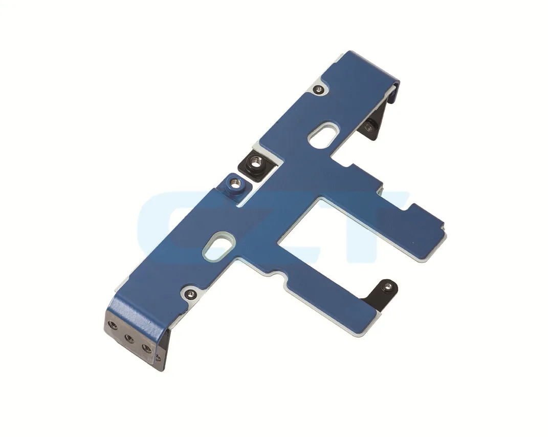
Laminated Busbar
Multiple thin copper layers laminated together with insulation between layers. Used in power electronics and battery systems.
Characteristics:
- Very low inductance
- Compact
- Used in: Inverters, UPS systems, battery packs, EV powertrains
3-Phase Busbar Sizing
Current Rating
Busbar current rating depends on:
- Cross-sectional area (mm²)
- Material (copper vs aluminum)
- Ambient temperature
- Enclosure type (open vs enclosed)
- Conductor arrangement
Approximate current ratings for copper busbars (open air, 40°C ambient):
| Width × Thickness | Cross-Section | Current Rating |
|---|---|---|
| 25 × 3 mm | 75 mm² | 280A |
| 40 × 5 mm | 200 mm² | 580A |
| 50 × 5 mm | 250 mm² | 700A |
| 60 × 10 mm | 600 mm² | 1,200A |
| 80 × 10 mm | 800 mm² | 1,500A |
| 100 × 10 mm | 1,000 mm² | 1,800A |
Derating factors:
- Enclosed in duct: ×0.8
- Ambient temperature >40°C: Derate per IEC 60439
- Multiple busbars in close proximity: Derate for mutual heating
Voltage Drop
For 3-phase systems, voltage drop across the busbar:
ΔV = √3 × I × (R·cosφ + X·sinφ) × L
Where:
- I = current (A)
- R = resistance per unit length (Ω/m)
- X = reactance per unit length (Ω/m)
- cosφ = power factor
- L = length (m)
Keep voltage drop below 1% for main distribution busbars.
Phase Arrangement
The standard phase arrangement for 3-phase busbars:
Horizontal arrangement (left to right): L1, L2, L3, N Vertical arrangement (top to bottom): L1, L2, L3, N Color coding (IEC 60446): L1=Brown, L2=Black, L3=Grey, N=Blue, PE=Green/Yellow
Consistent phase arrangement throughout a facility prevents phase reversal errors when connecting equipment.
Short-Circuit Rating
Busbars must withstand the prospective short-circuit current at their location. Short-circuit rating is expressed as:
- Icw: Rated short-time withstand current (kA for 1 second)
- Ipk: Peak withstand current (kA)
The busbar must be rated for the available fault current at the point of installation. This is determined by the upstream transformer impedance and system configuration.
Insulation and Clearances
Creepage distance: Minimum surface distance between conductors along insulating surfaces. Depends on voltage and pollution degree.
Clearance: Minimum air gap between conductors. For 400V systems: 25 mm minimum (IEC 61439).
Insulation materials:
- Epoxy resin: High mechanical strength, good electrical properties
- PVC: Lower cost, suitable for lower temperatures
- Polyamide (nylon): Good heat resistance
- Heat-shrink tubing: For field insulation of individual bars
Applications
| Application | Busbar Type | Typical Rating |
|---|---|---|
| Main switchboard | Open copper busbar | 1,000–6,300A |
| Motor control center | Open copper busbar | 400–2,000A |
| Factory power distribution | Busbar trunking | 400–4,000A |
| Data center power | Busbar trunking | 400–2,500A |
| Commercial building | Busbar trunking | 100–1,600A |
| Inverter/UPS | Laminated busbar | 100–2,000A |
Installation Considerations
-
Support spacing: Busbars must be supported at intervals to prevent sag and vibration. Typical support spacing: 600–1,200 mm.
-
Expansion joints: Long busbar runs need expansion joints to accommodate thermal expansion (copper expands ~17 µm/m/°C).
-
Connections: Bolted connections must be torqued to spec and use spring washers or Belleville washers to maintain contact pressure.
-
Maintenance access: Allow clearance for inspection, cleaning, and torque checking.
-
Labeling: Phase labels at regular intervals and at all connection points.
Summary
3-phase busbar systems are the most efficient way to distribute large amounts of power in industrial and commercial facilities:
- Open busbars: For switchgear and MCCs — high current, custom fabrication
- Busbar trunking: For building distribution — flexible, plug-in tap-offs
- Laminated busbars: For power electronics — low inductance, compact
Size busbars for continuous current plus derating factors, and verify short-circuit withstand rating.
CZT supplies busbar connectors, laminated busbars, and energy storage connection components. Browse our busbar and energy storage connector range.