Quick Answer
A pigtail connector is a short cable with a connector on one end and bare (stripped) wire or fiber on the other. In fiber optics, pigtails are fusion-spliced to field fiber inside splice trays — the most common termination method in telecom and data center networks. In electrical work, pigtails connect multiple wires to a single device terminal. Common fiber pigtail types include LC, SC, ST, and FC, available in single-mode (OS2) and multimode (OM3/OM4).
Need fiber pigtails or connectors? Browse CZT fiber optic products — LC, SC, and MPO pigtails and patch cords. Request a quote →
A pigtail connector is one of the most practical and widely used components in both electrical wiring and fiber optic networking. Whether you are splicing fiber in a telecom cabinet or wiring a receptacle in a commercial building, pigtail connectors simplify termination and improve connection reliability.
Despite their simplicity, pigtail connectors come in many forms. Electrical pigtails, fiber optic pigtails, and RF pigtails each serve different industries and follow different standards. Choosing the wrong type can lead to signal loss, safety hazards, or failed inspections.
This guide covers everything you need to know about pigtail connectors: what they are, how they work, the major types available, and how to select the right one for your application. If you are sourcing fiber optic connectors or automotive connectors for a project, this article will give you the technical foundation to make informed decisions.

What Is a Pigtail Connector?
A pigtail connector is a short length of wire, cable, or optical fiber that has a connector pre-terminated on one end and a bare, stripped, or unterminated end on the other. The bare end is designed to be spliced, soldered, crimped, or fused to another conductor or fiber in the field.
The term "pigtail" comes from the short, tail-like appearance of the cable. Unlike a patch cable, which has connectors on both ends, a pigtail gives you one factory-terminated connector and one open end for custom termination.
This design serves a specific purpose: it moves the most difficult part of the termination process — attaching the connector — to a controlled factory environment. Field technicians only need to handle the splice or crimp, which is faster and more reliable than attempting a full connector termination on-site.
Pigtail connectors are used across multiple industries:
- Electrical wiring — connecting devices to circuit wiring in junction boxes and panels
- Fiber optics — terminating fiber cables at patch panels and splice enclosures
- RF and coaxial — connecting antennas and radio equipment
- Automotive — sensor and harness connections in vehicles
- Solar energy — panel-to-inverter wiring
Electrical Pigtail Connectors
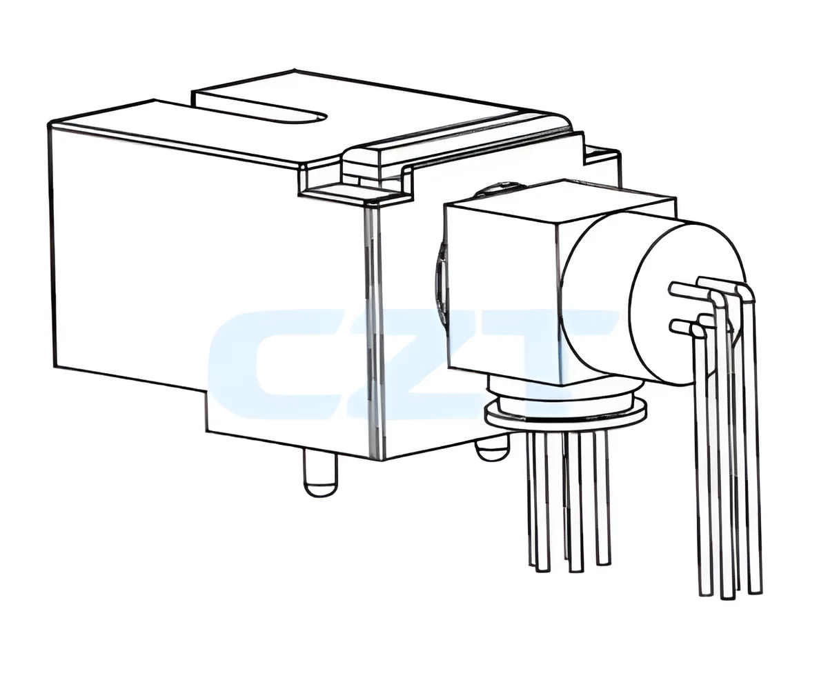
In electrical work, a pigtail wire connector is a short piece of insulated wire — typically 6 to 8 inches long — with one end stripped for connection to a device (outlet, switch, or fixture) and the other end stripped for splicing to circuit wiring using a wire nut or push-in connector.
Electrical pigtails solve a common problem. When multiple wires need to connect to a single device terminal, direct connections become crowded and unreliable. A pigtail creates a single, clean connection point: all circuit wires splice together with the pigtail using a wire nut, and the pigtail's other end connects to the device terminal.
Common Types of Electrical Pigtails
Grounding pigtails are the most common variety. These are short green or bare copper wires with a ring terminal or fork terminal on one end, designed to connect to the grounding screw on outlets and switches. They are required by the National Electrical Code (NEC) in many wiring configurations.
Device pigtails are used to connect receptacles and switches to branch circuit wiring. Instead of running multiple hot or neutral wires directly to the device, a single pigtail bridges the device to the splice.
Automotive pigtails are pre-wired connector assemblies used in vehicle electrical systems. These typically feature weatherproof connectors on one end (such as Deutsch, Metri-Pack, or Weather-Pack connectors) with stripped or tinned leads on the other. They are used to repair or extend wiring harnesses for sensors, lights, fuel injectors, and other vehicle components.
Why Electricians Use Pigtails
- Code compliance — The NEC requires pigtails in certain configurations, particularly for grounding continuity
- Reliability — If a device fails or is removed, the circuit wiring remains connected through the splice
- Safety — Reduces the number of wires on a single terminal, preventing loose connections
- Serviceability — Devices can be replaced without disturbing the circuit splice
Fiber Optic Pigtail Connectors
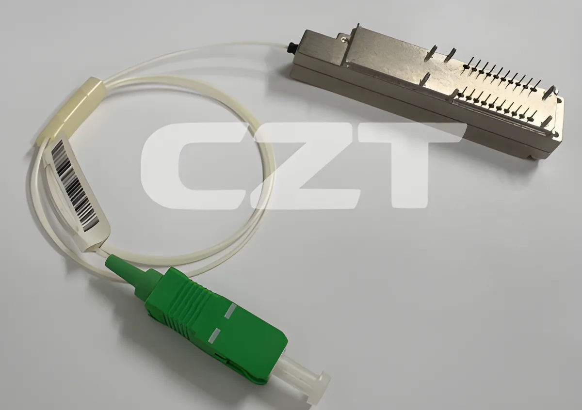
A fiber pigtail is a short length of optical fiber (typically 1 to 3 meters) with a factory-polished connector on one end and a bare, cleaved fiber on the other. The bare end is designed to be fusion spliced to an incoming fiber cable.
Fiber pigtails are essential in telecommunications and data center infrastructure. Fusion splicing a pigtail to a fiber cable produces a permanent, low-loss connection that is far superior to field-terminated connectors. The factory-polished connector end ensures consistent performance that meets or exceeds industry standards for insertion loss and return loss.
Fiber Pigtail Connector Types
| Connector Type | Ferrule Size | Latching Mechanism | Typical Use |
|---|---|---|---|
| LC | 1.25 mm | Push-pull latch | Data centers, high-density panels |
| SC | 2.5 mm | Push-pull snap | Telecom, FTTH, enterprise networks |
| ST | 2.5 mm | Bayonet twist-lock | Legacy networks, industrial |
| FC | 2.5 mm | Threaded screw-on | Test equipment, CATV, high-vibration |
| MPO/MTP | Multi-fiber | Push-pull | High-density parallel optics |
Single-Mode vs. Multi-Mode Fiber Pigtails
Single-mode pigtails (OS2, 9/125 um) are used for long-distance telecommunications, FTTH deployments, and DWDM systems. They carry a single light path and support transmission distances of up to 100 km or more. Single-mode pigtails are identified by their yellow jacket.
Multi-mode pigtails (OM1 through OM5, 50/125 or 62.5/125 um) are used for shorter-distance links within buildings and data centers. They support multiple light paths and are commonly used with 10G, 40G, and 100G Ethernet. Multi-mode pigtails use orange (OM1/OM2), aqua (OM3/OM4), or lime green (OM5) jackets.
Fiber Pigtail Specifications
A quality fiber pigtail should meet these performance benchmarks:
| Parameter | Single-Mode (PC) | Single-Mode (APC) | Multi-Mode |
|---|---|---|---|
| Insertion Loss | ≤ 0.3 dB | ≤ 0.3 dB | ≤ 0.3 dB |
| Return Loss | ≥ 50 dB | ≥ 60 dB | ≥ 20 dB |
| Fiber Length | 1 - 3 m | 1 - 3 m | 1 - 3 m |
| Operating Temp | -40 to +85 C | -40 to +85 C | -40 to +75 C |
APC (Angled Physical Contact) pigtails feature an 8-degree angled ferrule end face that reduces back reflections. They are identified by their green connector housing and are required in FTTH, CATV, and other applications sensitive to return loss.
APC vs UPC vs PC Polish Types
The polish type on a fiber connector's ferrule end face directly determines return loss performance and dictates which applications the connector can serve. Understanding the three polish types — PC, UPC, and APC — is essential for specifying fiber pigtails correctly.
PC (Physical Contact) connectors use a slightly curved dome polish that ensures the two fiber cores make physical contact when mated. PC polish achieves return loss of approximately -30 dB. This was the original fiber connector polish type and is rarely specified in new installations, having been superseded by UPC and APC in virtually all modern deployments.
UPC (Ultra Physical Contact) connectors refine the PC approach with an extended polishing process that produces a finer surface finish on the ferrule end face. UPC achieves return loss of -55 dB or better — a significant improvement over standard PC. UPC connectors are identified by their blue connector housing and are the default choice for datacom applications, including Ethernet switches, media converters, and SFP/SFP+ transceivers in enterprise and data center environments.
APC (Angled Physical Contact) connectors polish the ferrule end face at an 8-degree angle, which causes reflected light to escape into the cladding rather than traveling back down the fiber core. This design achieves return loss of -65 dB or better. APC connectors are identified by their green connector housing and are required in applications sensitive to back-reflection, including CATV, FTTH (GPON/XGS-PON), WDM systems, and analog video transmission.
Polish Type Comparison
| Polish Type | Return Loss | Connector Color | Best For |
|---|---|---|---|
| PC | ≥ -30 dB | Beige / uncolored | Legacy installations, test setups |
| UPC | ≥ -55 dB | Blue | Ethernet, datacom, digital video |
| APC | ≥ -65 dB | Green | FTTH, CATV, WDM, analog signals |
CRITICAL: APC and UPC connectors are NOT interchangeable. The 8-degree angle on APC ferrules means that mating an APC connector with a UPC connector creates an air gap between the fiber cores. This air gap causes high insertion loss, elevated back-reflections, and — most importantly — permanent physical damage to both ferrule end faces. Always verify polish type compatibility before making any fiber connection. If the connector housings are different colors, do not mate them.
Fiber Pigtail Color Coding Guide
Fiber pigtail jacket color is standardized by TIA/EIA-598 and provides immediate visual identification of the fiber grade. In a busy splice enclosure or patch panel, correct color identification prevents cross-connecting incompatible fiber types.
| Fiber Grade | Jacket Color | Core/Cladding (μm) | Typical Application |
|---|---|---|---|
| OS2 (Single-Mode) | Yellow | 9/125 | Long-haul telecom, FTTH, WDM |
| OM1 (Multimode) | Orange | 62.5/125 | Legacy LANs (100 Mbps - 1 Gbps) |
| OM2 (Multimode) | Orange | 50/125 | Legacy LANs (1 Gbps) |
| OM3 (Multimode) | Aqua | 50/125 | 10G/40G data center (≤300m/100m) |
| OM4 (Multimode) | Aqua / Violet | 50/125 | 10G/40G/100G data center (≤400m/150m/100m) |
| OM5 (Multimode) | Lime Green | 50/125 | SWDM, 40G/100G over fewer fibers |
Ribbon Fiber Pigtails
Ribbon fiber pigtails bundle 12 or 24 individual fibers into a flat, parallel ribbon structure, with all fibers terminated to connectors at one end and presented as bare ribbon fiber at the other. These pigtails are designed for high-density data center environments where MPO/MTP connectors serve as the standard interface for parallel optic links.
The primary advantage of ribbon pigtails is compatibility with mass fusion splicing. A ribbon fusion splicer aligns and splices all 12 fibers simultaneously in a single operation, compared to splicing individual fibers one at a time. This capability dramatically reduces installation time in large-count fiber deployments — a 144-fiber cable that would require 144 individual splices can be completed in just 12 ribbon splice operations. For hyperscale data centers and carrier-grade central offices handling hundreds or thousands of fiber strands, ribbon pigtails are the only practical termination method.
Types of Pigtail Connectors
Pigtail connectors can be categorized by application, connector type, and conductor specifications. The table below provides a high-level comparison of the three main categories.
Pigtail Connector Comparison by Category
| Category | Conductor | Connector Examples | Typical Length | Key Specification |
|---|---|---|---|---|
| Electrical | Copper wire (12-18 AWG) | Ring terminal, fork terminal, wire nut | 6 - 12 inches | Wire gauge, voltage rating |
| Fiber Optic | Glass or plastic fiber | LC, SC, ST, FC, MPO | 1 - 3 meters | Insertion loss, return loss |
| RF / Coaxial | Coaxial cable | SMA, N-type, BNC, TNC | 6 - 24 inches | Frequency range, VSWR |
By Connector Type
Electrical pigtail connectors are available with ring terminals, fork (spade) terminals, quick-disconnect (blade) terminals, butt splice connectors, and bare stripped ends. The choice depends on the termination point — ring terminals for screw connections, quick-disconnects for tab connections, and bare ends for wire nut splices.
Fiber optic pigtail connectors are available in every standard fiber connector format. LC pigtails dominate in data centers due to their small form factor and high port density. SC pigtails remain the standard for FTTH and telecom applications. ST and FC pigtails are found in legacy installations and specialized industrial or test environments.
RF pigtail cables use coaxial connectors such as SMA, RP-SMA, N-type, BNC, and U.FL/IPEX. These are common in wireless networking, antenna installations, and test and measurement setups. RF pigtails are specified by impedance (typically 50 ohm), frequency range, and cable type (RG-174, RG-316, LMR-195).
By Wire Gauge (Electrical)
| Wire Gauge (AWG) | Typical Ampacity | Common Application |
|---|---|---|
| 18 AWG | 7A | Low-voltage lighting, thermostats |
| 16 AWG | 10A | Light-duty appliances |
| 14 AWG | 15A | General-purpose 15A circuits |
| 12 AWG | 20A | Kitchen, bathroom, garage 20A circuits |
| 10 AWG | 30A | Dryers, water heaters, AC units |
Always match the pigtail wire gauge to the circuit rating. Using an undersized pigtail creates a fire hazard and violates electrical codes.
Pigtail Connector Applications
Pigtail connectors serve critical roles across a wide range of industries. Here are the most common applications.
Telecommunications
Fiber pigtails are the standard method for terminating fiber optic cables at central offices, remote terminals, and optical distribution frames. Technicians fusion splice pigtails to incoming fiber strands, then plug the connectorized end into patch panels or optical line terminals (OLTs). This approach is used in FTTH, FTTB, and long-haul backbone networks worldwide.
Electrical Panels and Junction Boxes
Electricians use pigtail wire connectors to maintain circuit continuity when connecting outlets, switches, and fixtures. Pigtailing is especially important in multi-gang boxes where several devices share a single circuit. It ensures that removing one device does not break the circuit to downstream devices.
Automotive
Automotive pigtail connectors are used to repair damaged wiring harnesses, add aftermarket accessories, and replace failed sensors or actuators. Pre-terminated pigtails with OEM-compatible connectors (Deutsch DT/DTM, Delphi Metri-Pack, TE Superseal) save hours of labor compared to sourcing and crimping individual pins. Common automotive pigtail applications include oxygen sensors, fuel injectors, ignition coils, lighting harnesses, and trailer connectors.
Solar Energy
In photovoltaic systems, pigtail cables connect solar panels to junction boxes, optimizers, and inverters. Solar pigtails typically feature MC4-compatible connectors on one end and stripped or tinned leads on the other. They must be UV-resistant, rated for outdoor exposure, and sized for the panel's maximum current output.
Data Centers and Enterprise Networking
Fiber pigtails are used in high-density patch panel termination, pre-terminated cassette assemblies, and splice-on connector solutions. LC pigtails are the dominant choice for 10G, 25G, and 100G Ethernet links. MPO pigtails support parallel optics and breakout applications in spine-leaf architectures.
How to Use a Pigtail Connector
The installation process depends on whether you are working with electrical pigtails or fiber optic pigtails.
Electrical Pigtail Installation
- Turn off power at the circuit breaker and verify with a voltage tester.
- Cut the pigtail wire to the appropriate length — typically 6 to 8 inches. Use the same gauge as the circuit wiring.
- Strip the ends — remove approximately 3/4 inch of insulation from each end of the pigtail.
- Group the wires — hold the pigtail wire together with the circuit wires that need to be spliced (e.g., all hot wires or all neutral wires).
- Twist and cap — twist the bare ends together clockwise and secure with an appropriately sized wire nut. Tug each wire to confirm a solid connection.
- Connect to the device — attach the pigtail's free end to the device terminal using the screw terminal or push-in connector.
- Fold wires carefully into the junction box and install the device.
Fiber Optic Pigtail Installation (Fusion Splice)
- Prepare the fiber cable — strip the outer jacket, buffer tubes, and coating to expose bare fiber. Clean with isopropyl alcohol.
- Cleave the fiber — use a precision cleaver to create a flat, perpendicular end face on the incoming fiber.
- Load the fibers — place the pigtail's bare fiber and the incoming fiber into the fusion splicer's V-grooves.
- Align and splice — the splicer automatically aligns the fiber cores and fuses them with an electric arc. A quality splice produces less than 0.05 dB of loss.
- Protect the splice — slide a heat-shrink splice protector over the splice point and cure it in the splicer's heater.
- Route and store — place the completed splice in a splice tray, maintaining the minimum bend radius (typically 30 mm for standard fiber).
- Connect — plug the pigtail's connector end into the patch panel, ODF, or equipment port.

Mechanical Splice vs Fusion Splice
When terminating fiber pigtails to field cable, technicians choose between two splicing methods: fusion splicing and mechanical splicing. Each has distinct trade-offs in performance, cost, and deployment context.
Fusion splicing uses a precision electric arc to permanently meld two cleaved fiber ends into a single continuous strand. The splicer automatically aligns the fiber cores using a camera system, then fires a controlled arc that fuses the glass at approximately 2,000°C. A quality fusion splice produces 0.02 to 0.05 dB of typical loss — essentially transparent to the optical signal. The trade-off is equipment cost: fusion splicers range from $3,000 for basic single-fiber units to $15,000 or more for high-end ribbon splicers with advanced core alignment. Fusion splicing is the standard method for permanent telecom infrastructure, FTTH deployments, and data center backbone cabling.
Mechanical splicing aligns two cleaved fiber ends inside a small V-groove or tube assembly filled with index-matching gel. The gel eliminates the air gap between the fiber ends, and a clamping mechanism holds the fibers in alignment. Mechanical splices produce 0.1 to 0.5 dB of typical loss — acceptable for many applications but notably higher than fusion. Each mechanical splice costs approximately $5 to $15 in materials, and no expensive equipment is required beyond a cleaver and basic hand tools. Mechanical splicing is used for emergency fiber restoration, temporary connections, and situations where a fusion splicer is unavailable or impractical.
Splice Method Comparison
| Parameter | Fusion Splice | Mechanical Splice |
|---|---|---|
| Typical Loss | 0.02 - 0.05 dB | 0.1 - 0.5 dB |
| Equipment Cost | $3,000 - $15,000 | $50 - $200 (cleaver + tool kit) |
| Per-Splice Cost | ~$0.50 (splice protector) | $5 - $15 (splice unit + gel) |
| Speed | ~2 minutes per splice | ~5 minutes per splice |
| Permanence | Permanent | Semi-permanent (removable) |
| Best For | Permanent infrastructure | Emergency repairs, temporary links |
| Skill Level | Moderate (splicer automates alignment) | Lower (manual alignment) |
For pigtail termination in production environments, fusion splicing is nearly always the preferred method. The lower per-splice loss adds up across large fiber counts, and the permanent bond eliminates the risk of splice degradation over time. Mechanical splices are best reserved for field repairs and low-fiber-count temporary installations where deploying a fusion splicer is not justified.
Pigtail vs. Patch Cable: What's the Difference?
This is one of the most common questions in both electrical and fiber optic work. While pigtails and patch cables look similar, they serve fundamentally different purposes.
| Feature | Pigtail | Patch Cable |
|---|---|---|
| Connectors | One end only | Both ends |
| Purpose | Permanent termination (splice/crimp) | Temporary or semi-permanent link |
| Installation | Spliced or crimped in the field | Plug-and-play |
| Typical Use | Splice enclosures, junction boxes | Equipment-to-panel connections |
| Removability | Permanent on the splice side | Fully removable |
| Cost | Lower (one connector) | Higher (two connectors) |
When to use a pigtail: Use a pigtail when you need to terminate a raw cable (fiber or copper) with a connector. Pigtails are the right choice when the cable will be permanently installed and the connection needs to be as reliable as possible. In fiber optics, fusion-spliced pigtails consistently outperform field-terminated connectors in insertion loss and return loss.
When to use a patch cable: Use a patch cable when you need a removable connection between two pieces of equipment or between equipment and a patch panel. Patch cables are designed to be plugged and unplugged repeatedly.
In many fiber optic installations, both are used together: pigtails terminate the permanent cabling at the patch panel, and patch cables connect the panel ports to active equipment.
Choosing the Right Pigtail Connector
Selecting the correct pigtail connector requires matching several parameters to your application. Here are the key factors to evaluate.
1. Application Type
Determine whether you need an electrical, fiber optic, or RF pigtail. This narrows the field immediately and dictates the relevant specifications.
2. Connector Type
For fiber optics, match the pigtail connector to your patch panel and equipment ports. LC is the current standard for most data center and enterprise applications. SC is standard for telecom and FTTH. For electrical work, match the terminal type to the device connection method.
3. Wire Gauge or Fiber Type
Electrical pigtails must match the circuit wire gauge. Never use a smaller gauge pigtail than the circuit requires. For fiber, choose single-mode (OS2) for long-distance telecom or multi-mode (OM3/OM4/OM5) for short-reach data center links.
4. Length
Electrical pigtails are typically 6 to 12 inches. Fiber pigtails range from 1 to 3 meters. Choose a length that provides enough slack for routing and splice tray management without excessive coiling.
5. Environmental Conditions
Consider temperature range, moisture exposure, UV exposure, and chemical resistance. Outdoor and industrial applications require pigtails with ruggedized jackets, IP-rated connectors, or UV-stabilized materials. Automotive pigtails must meet temperature and vibration requirements specific to the vehicle zone.
6. Certifications and Standards
Look for pigtails that meet relevant industry standards:
- Electrical — UL listed, NEC compliant
- Fiber optic — Telcordia GR-326, IEC 61753
- Automotive — USCAR, SAE, OEM-specific standards
- RF — MIL-STD specifications where applicable
7. Manufacturer Quality
Factory-polished fiber pigtail connectors should come with individual test reports showing insertion loss and return loss values. Electrical pigtails should use oxygen-free copper conductors and properly rated insulation. Sourcing from an ISO 9001-certified manufacturer ensures consistent quality across production lots.
Pigtailing Electrical Outlets: Step-by-Step
Pigtailing outlets is one of the most important wiring practices for residential and commercial electrical work. When you pigtail an outlet, you connect a short electrical wire pigtail between the device terminal and a splice of all circuit wires — rather than running circuit wires directly through the device using screw terminals or backstab connections.
Why Pigtailing Outlets Matters
The most critical reason to pigtail is circuit continuity. When outlets are wired in series using the device's terminal screws (daisy-chaining), the circuit path runs through each outlet. If any single outlet fails, loosens, or is removed for replacement, every downstream outlet on that circuit loses power. Pigtailed wiring eliminates this single point of failure — the circuit wires are spliced together independently, and each outlet connects via its own pigtail.
When Pigtailing Is Required
- NEC 300.13(B) requires that the continuity of a grounded (neutral) conductor must not depend on device connections. In practice, this means neutral wires in multi-wire branch circuits must be pigtailed.
- Grounding continuity — the NEC requires that removing a device must not interrupt the grounding path. Pigtailing the ground wire is standard practice.
- Multiple conductors on a single terminal — most residential devices are rated for only one wire per terminal. Pigtailing is the correct way to serve multiple wires from one device.
How to Pigtail an Electrical Outlet
- Turn off power at the breaker and verify with a non-contact voltage tester
- Cut pigtail wires — cut three pigtails (hot, neutral, ground) from matching-gauge wire, each 6–8 inches long
- Strip wire ends — strip 3/4 inch of insulation from each end
- Splice circuit wires — hold all circuit hot wires together with the hot pigtail, twist clockwise, and cap with a wire nut sized for the wire count. Repeat for neutral wires. For ground wires, use a green wire nut or ground crimp.
- Connect pigtails to outlet — attach the hot pigtail (black) to the brass-colored terminal, neutral pigtail (white) to the silver terminal, and ground pigtail (green/bare) to the green grounding screw
- Fold and install — carefully fold wires into the box and mount the outlet
Pigtailing Outlets: Tips for Reliability
- Match wire gauge exactly — a 20A circuit (12 AWG) requires 12 AWG pigtails. Never downsize.
- Use the correct wire nut — wire nuts are rated by wire count and gauge. An undersized nut will not grip properly.
- Tug-test every splice — gently pull each wire after capping to confirm the nut is tight.
- Leave enough slack — 6 inches is minimum. Too-short pigtails make the box difficult to work in and increase the risk of wires pulling loose when you push the device in.

Pigtail Splicing Techniques
Pigtail splicing refers to the methods used to join a pigtail connector to the existing wiring — whether that wiring is copper electrical wire or optical fiber. Each conductor type requires a different splicing technique, and choosing the right one affects performance, safety, and longevity.
Electrical Pigtail Splicing Methods
| Method | Tools Required | Best For | Reliability |
|---|---|---|---|
| Wire nut | Wire stripper, pliers | Standard residential/commercial | High (when properly torqued) |
| Push-in connector (Wago-style) | Wire stripper only | Quick connections, solid wire | High (rated for 600V, 20A) |
| Crimp splice | Crimping tool, butt splice | Automotive, industrial | Very high (vibration-resistant) |
| Solder + heat shrink | Soldering iron, heat gun | Permanent, low-resistance joints | Very high (but labor-intensive) |
Wire nut splicing is the most common method for electrical pigtails in building wiring. Strip 3/4 inch of insulation, hold wires parallel, and twist the wire nut clockwise until tight. The nut's internal spring coil grips the conductors and insulates the splice. Always tug-test after tightening.
Push-in (lever) connectors like Wago 221 series have largely replaced wire nuts in many commercial installations. They accept solid or stranded wire, provide a visible inspection window, and are re-openable — making them faster to install and easier to troubleshoot than wire nuts. They are rated for the same voltage and amperage as wire nuts.
Fiber Optic Pigtail Splicing Methods
For fiber optic pigtails, splicing is covered in detail in the fusion splice vs mechanical splice section above. In brief:
- Fusion splicing — permanent, lowest loss (0.02–0.05 dB), standard for all production fiber installations
- Mechanical splicing — semi-permanent, higher loss (0.1–0.5 dB), used for emergency repairs and temporary connections
For fiber-related pigtails used with SFP transceiver modules, the pigtail connector type (LC, SC) must match the transceiver's optical interface.
Frequently Asked Questions
What is a pigtail connector used for?
A pigtail connector is used to terminate a raw wire or fiber optic cable with a pre-made connector. In electrical work, pigtails connect devices to circuit wiring through a splice. In fiber optics, pigtails are fusion spliced to fiber cables to provide a connectorized termination point at patch panels and distribution frames.
What is the difference between a pigtail and a jumper cable?
A pigtail has a connector on only one end, with the other end bare for splicing or crimping. A jumper (patch cable) has connectors on both ends and is designed for plug-and-play connections. Pigtails create permanent terminations, while jumpers create removable links.
How long should an electrical pigtail be?
The NEC does not specify a minimum pigtail length, but industry best practice is 6 to 8 inches. This provides enough length to make connections comfortably while keeping the junction box manageable. Some local codes may specify minimum lengths, so check your jurisdiction's requirements.
Can I use a different wire gauge for a pigtail?
No. The pigtail wire gauge must match or exceed the circuit wire gauge. Using a smaller gauge pigtail creates a bottleneck that can overheat under load, posing a fire risk and violating electrical codes. For example, a 20A circuit wired with 12 AWG requires a 12 AWG pigtail.
What is the typical insertion loss for a fiber optic pigtail?
A quality fiber optic pigtail should have an insertion loss of 0.3 dB or less. Premium pigtails from reputable manufacturers typically achieve 0.1 to 0.2 dB. The return loss should be 50 dB or greater for PC polish and 60 dB or greater for APC polish. Always request test data from your supplier.
CZT manufactures fiber optic pigtails, electrical pigtail connectors, and custom cable assemblies backed by 30+ years of connector engineering expertise and ISO 9001 certification. Whether you need standard pigtails or custom-length assemblies with specific connector configurations, our engineering team can deliver to your specifications. Request a Quote →


