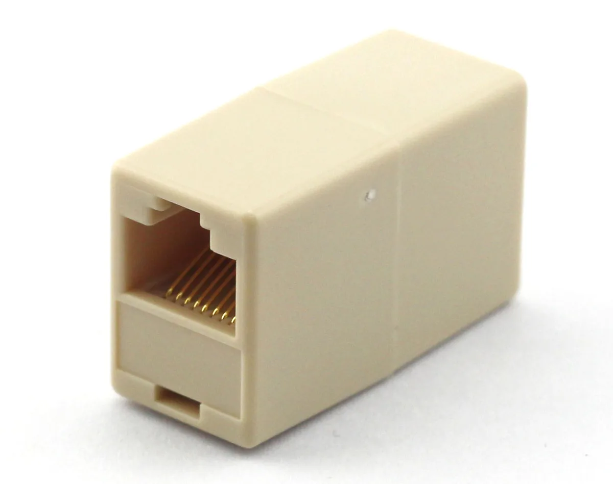
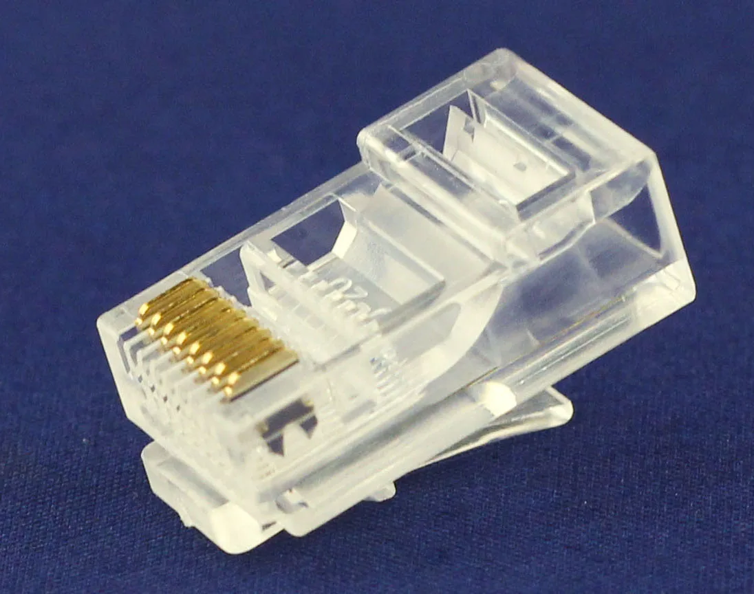
A legacy connector sample can start a specification effort, but it cannot reveal every property needed to approve a replacement. Separate measurable interface geometry from inferred materials, hidden construction and unverified performance. The goal is a controlled requirements package for a new proposal, not a claim that visual similarity proves equivalence.
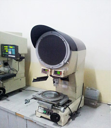
Figure 1. CZT optical-inspection equipment. Physical measurement can help define a lawful legacy sample when drawings are absent. CZT source · Original image.
Establish provenance and permission
Record where the sample came from, its equipment application and whether it is new, used or damaged. Confirm that the organization is authorized to provide it for measurement and the intended sourcing work. Preserve any existing markings and assembly photographs.
Decide which specimen can be used for nondestructive measurement and whether destructive analysis is permitted. A worn contact or bent housing can be a poor dimensional reference. Keep that condition visible rather than treating every observed dimension as the original design intent.
Measure the functional interfaces first
Identify the mating counterpart, mounting method and installed clearances. Record the dimensions that control seating, alignment, retention and access. Where possible, measure several identified samples to expose variation without pretending that a small set establishes manufacturing tolerances.
For a cable assembly, add circuit mapping, length datums and strain-relief geometry. CZT's wire-harness family includes the catalog example LED Wire Harness. That identity is a starting point for discussing an assembly type, not evidence that it replaces an unknown legacy lead or shares its electrical mapping.
Separate observations from open requirements
| Characteristic | What a sample may show | What still needs confirmation |
|---|---|---|
| Outer geometry | Measured dimensions and condition | Original tolerances and datums |
| Mating interface | Physical form and observed engagement | Approved counterpart and verification |
| Conductive path | Observed continuity | Intended circuit and operating limits |
| Material or finish | Appearance or identified analysis result | Controlled material specification |
| Performance | Results of defined tests | Required qualification and covered conditions |
The table prevents an inferred property from entering the purchase drawing as an established fact.

Figure 2. CZT coordinate-measurement equipment. A second metrology method illustrates why measured geometry and unknown material or performance characteristics must remain separate. CZT source · Original image.
Build and validate a proposed specification
Use equipment requirements to fill the gaps that the sample cannot settle. Request a supplier proposal with controlled drawings, declared materials and the planned evidence. Mark any dimension derived from a worn or uncertain feature for particular review.
A hypothetical housing may fit the same opening while using a different retention feature. That can be acceptable in a redesigned assembly or unsuitable in existing equipment; the decision depends on the installed requirement, not resemblance alone.
Document which sample features appear altered by use. A worn latch or crushed seal can explain a measured shape without establishing the intended replacement geometry. Preserve that uncertainty in the drawing review.
Approve the new part through representative fit, function and relevant qualification checks. Retain the legacy observations separately from the new proposal's verified results. This creates a supportable replacement specification without inventing the missing original data or allowing a single surviving sample to stand in for a complete engineering record.
Connect this review to CZT product information
Examples for applying this worksheet are listed below. Use the identifiers to request the current drawing and confirm the configuration required by your application.
| Catalog reference | Product information | Drawing record | Reference inquiry |
|---|---|---|---|
| QWY-1062-7 | 4001 Series 8-position modular socket, QWY-1062-7 | Listed PDF | Ask about this reference |
| QWY-1013-10 | 8P8C modular plug, QWY-1013-10 | Listed PDF | Ask about this reference |
A catalog drawing reference is a starting document, not a substitute for reviewing its revision, options and suitability for the complete assembly.
Browse the relevant product family · View catalog resources
Discuss a drawing, sample or quotation
Share the part or family reference, current drawing revision, operating conditions and quantities. Include the specific checks described in this article so the inquiry identifies both the component and the evidence needed for your decision. Confirm sample availability and the proposed scope with the supplier.
Request a technical review or quotation
For broader context, read the related selection guide.