Accept MPO system polarity by checking the complete channel map across trunks, cassettes and patch cords. A label describing one cable's polarity does not establish the behavior of the assembled system. Write the required end-to-end map first, then verify that each supplied component preserves the intended channel relationship.
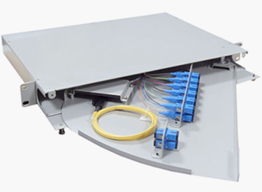
Figure 1. Official distribution-unit illustration provides context for channel mapping across assemblies; it is not presented as an MPO cassette or verified polarity example. CZT source · Original image.
Draw the channel chain
Identify every optical interface and its fiber-position numbering. State the view direction, key orientation and relevant pinned or unpinned construction at each connection. Include cassette internals and breakouts rather than drawing them as unlabeled boxes.
Fluke Networks' data-center fiber guidance notes the greater polarity-management complexity of multifiber connectivity. Use the actual assembly drawings and relevant current cabling requirements to resolve the map; a general Type A, B or C description is not a complete system drawing.
Match components to the intended system
Check fiber count, interface geometry, polish, keying and pin configuration separately from channel mapping. A component can have the desired mapping but the wrong mechanical or optical interface. Do not let one field marked MPO compatible substitute for those distinct checks.
CZT's fiber-optic product family supports an interface-consultation inquiry. The specifically identified catalog fiber example is SC-to-FC. It is not evidence of an available MPO trunk, cassette or breakout, so confirm any such proposal before assigning a product code.
Use an end-to-end acceptance table
| Record group | Information to retain |
|---|---|
| Endpoints | Equipment ports and required channel destinations |
| Components | Exact trunk, cassette, adapter and patch-cord identities |
| Mechanical interfaces | Pin state, key orientation and connector construction |
| Mapping | Position-by-position route through every stage |
| Test evidence | Measured continuity or polarity map and sample IDs |
| Disposition | Approved map or specific unresolved mismatch |
The test method must distinguish individual fiber positions. A successful connection on one channel cannot establish the mapping of the remaining fibers.
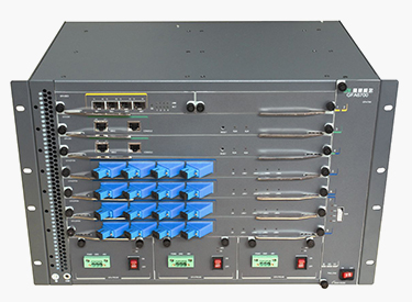
Figure 2. Official optical-equipment illustration highlights multiple connection boundaries that require explicit channel identities in an end-to-end acceptance record. CZT source · Original image.
Validate the installed combination
Inspect and prepare the optical interfaces using the selected equipment's appropriate procedures, then measure the complete map. Preserve the original results if a component is reversed or replaced to correct a mismatch. Retest the changed channel chain rather than assuming the repair affected only one connection.
A hypothetical system can use correctly labeled trunks and correctly labeled cassettes yet form an unintended end-to-end map because the chosen combination was not the designed one. Component correctness and system correctness are separate conclusions.
Include unused fiber positions in the mapping record rather than omitting them. They may become active during an upgrade or breakout change. Recording their actual destinations now can prevent a later expansion from relying on an assumed internal cassette arrangement.
Keep the validated combination as a controlled assembly record. If a cassette supplier, trunk polarity option or patch-cord arrangement changes, revisit the map and interface checks. That makes later expansion and spare-part replacement traceable to the actual accepted channel structure instead of to a broad cable-family label.
Connect this review to CZT product information
For LC, MPO, polish or polarity requirements, start with the fiber-optic product family. The available SC-to-FC assembly record is a different interface and is not presented here as a matching LC or MPO part. Ask CZT to confirm the exact configuration and available documentation.
Browse the relevant product family · View catalog resources
Discuss a drawing, sample or quotation
Share the part or family reference, current drawing revision, operating conditions and quantities. Include the specific checks described in this article so the inquiry identifies both the component and the evidence needed for your decision. Confirm sample availability and the proposed scope with the supplier.
Request a technical review or quotation
For broader context, read the related selection guide.