Quick Answer
T568B is the dominant standard in North America and most commercial installations. T568A is required by US federal contracts (TIA-568 Annex A) and common in some European and Asian markets. Both use the same 8P8C RJ45 plug — only the color-code order of two pairs differs. Use the same standard on both ends of a patch cable to make a straight-through cable. For complete pinout tables, crimping steps, and compatibility details, keep reading.
Need RJ45 connectors for your project? Browse CZT RJ45 connectors — Cat5e through Cat6a, shielded and unshielded, with PoE support. Request a quote →
Every wired Ethernet connection on the planet terminates in an RJ45 connector. From a single desk drop in a home office to a 10,000-port data center, the same 8-pin modular plug carries the signal. Yet a surprising number of network failures trace back to one simple problem: incorrect pinout wiring.
Two wiring standards govern how the eight colored wires inside an Ethernet cable map to the eight pins of an RJ45 plug — T568A and T568B. Use the wrong one, or mix them on opposite ends, and you get crosstalk, packet loss, or a dead link.
This guide gives you the complete rj45 pinout for both standards, side-by-side comparison tables, crimping instructions, and the technical context to choose correctly every time. Whether you are pulling Cat5e for a small office or specifying Cat6 RJ45 connectors for a campus backbone, the information here applies.
What Is an RJ45 Connector?
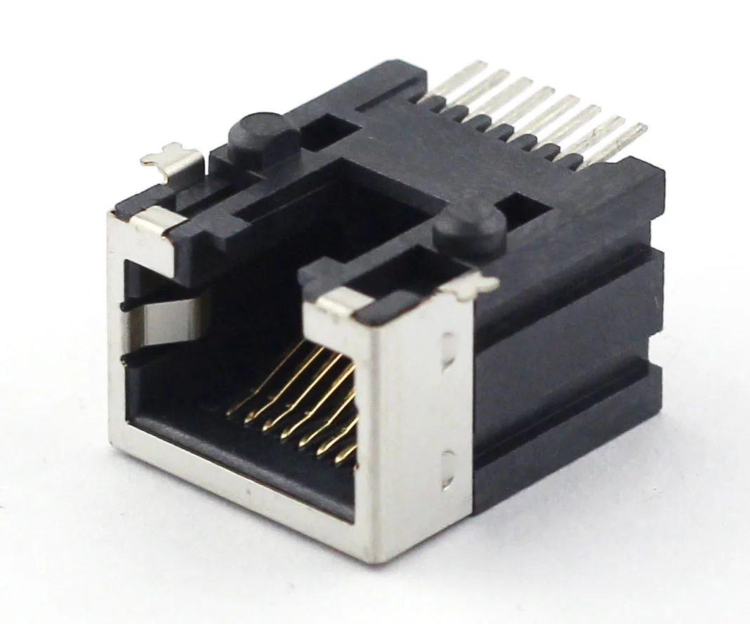
The term "RJ45" technically refers to a specific wiring configuration registered with the FCC, but in everyday use it describes the 8P8C (8-position, 8-contact) modular connector used for Ethernet networking. It is the most widely deployed data connector in the world.
Physical characteristics
- 8 gold-plated contacts arranged in a single row inside a clear or tinted plastic housing.
- Locking tab (clip) on the underside that snaps into a mating jack and prevents accidental disconnection.
- Strain relief boot (on quality plugs) that protects the cable jacket at the entry point.
- Accepts 22–26 AWG solid or stranded conductors, depending on the plug variant.
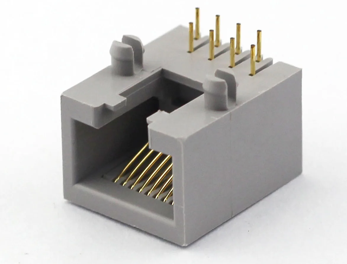
An RJ45 connector mates with an 8P8C jack — the rectangular port found on network switches, routers, patch panels, and computer NICs. The mechanical interface is standardized, but the electrical pinout depends on which wiring scheme you follow.
Where RJ45 connectors are used
| Application | Typical cable | Speed |
|---|---|---|
| Home / office LAN | Cat5e | 1 Gbps |
| Enterprise backbone | Cat6 / Cat6a | 10 Gbps |
| PoE devices (cameras, APs) | Cat5e / Cat6 | 1 Gbps + 30–90 W power |
| Industrial Ethernet | Cat6a shielded | 10 Gbps |
| Telecom / data center | Cat6a / Cat8 | 10–25 Gbps |
CZT has manufactured over 1 billion RJ45 connectors per year for more than three decades. The pinout information in this guide reflects the TIA/EIA-568 standard that governs every unit we produce.
RJ45 Pin Numbering
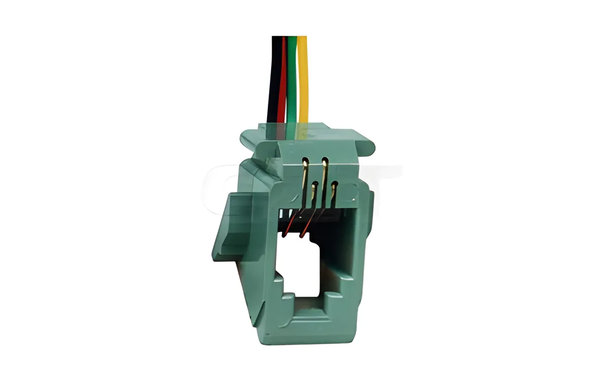
Before you can follow any rj45 wiring diagram, you need to know how the pins are numbered. Get the orientation wrong and every wire lands in the wrong position.
How to orient the plug
- Hold the RJ45 plug with the clip (locking tab) facing away from you (pointing down).
- Turn the plug so the gold contacts face toward you.
- Pin 1 is on the far left. Pin 8 is on the far right.
| Pin | Position |
|---|---|
| Pin 1 | Far left |
| Pin 2 | Second from left |
| Pin 3 | Third from left |
| Pin 4 | Fourth from left (center-left) |
| Pin 5 | Fifth from left (center-right) |
| Pin 6 | Sixth from left |
| Pin 7 | Seventh from left |
| Pin 8 | Far right |
This numbering is identical for plugs and jacks. On a keystone jack or patch panel port, the pin numbers are usually printed on the PCB or label.
T568A Wiring Standard
The T568A standard is defined in ANSI/TIA-568. It specifies the following color-to-pin mapping for an rj45 connector plug.
T568A pinout table
| Pin | Wire color | Pair | Function (10/100BASE-T) |
|---|---|---|---|
| 1 | White/Green | Pair 3 | TX+ |
| 2 | Green | Pair 3 | TX− |
| 3 | White/Orange | Pair 2 | RX+ |
| 4 | Blue | Pair 1 | Unused |
| 5 | White/Blue | Pair 1 | Unused |
| 6 | Orange | Pair 2 | RX− |
| 7 | White/Brown | Pair 4 | Unused |
| 8 | Brown | Pair 4 | Unused |
When to use T568A
- U.S. federal government installations. TIA-568 designates T568A as the preferred standard, and U.S. government contracts often mandate it.
- Residential wiring. T568A aligns with the USOC wiring scheme used for telephone lines, making it easier to support both voice and data on the same cabling infrastructure.
- New installations where no existing standard is in place. If you are starting from scratch and have no legacy cabling to match, T568A is the officially recommended choice.
The key detail: Pair 2 (orange) sits on pins 3 and 6, while Pair 3 (green) sits on pins 1 and 2. This is the opposite of T568B.
T568B Wiring Standard
T568B is the other recognized wiring scheme in the TIA/EIA-568 standard. It is the most widely used pinout in commercial and enterprise networking.
T568B pinout table
| Pin | Wire color | Pair | Function (10/100BASE-T) |
|---|---|---|---|
| 1 | White/Orange | Pair 2 | TX+ |
| 2 | Orange | Pair 2 | TX− |
| 3 | White/Green | Pair 3 | RX+ |
| 4 | Blue | Pair 1 | Unused |
| 5 | White/Blue | Pair 1 | Unused |
| 6 | Green | Pair 3 | RX− |
| 7 | White/Brown | Pair 4 | Unused |
| 8 | Brown | Pair 4 | Unused |
When to use T568B
- Commercial buildings and enterprise networks. The vast majority of installed structured cabling in offices, campuses, and data centers follows T568B.
- Matching existing infrastructure. If the patch panels and wall jacks in a building are already wired to T568B, every new run should match.
- Industry convention. Most pre-made patch cables sold at retail are terminated T568B on both ends.
The mnemonic many installers use for T568B: "Orange starts first." White/Orange on Pin 1, Orange on Pin 2.
T568A vs T568B: What's the Difference?
Electrically, both standards deliver identical performance. The difference is purely about which color-coded pairs land on which pins. Here is a direct comparison.
Side-by-side comparison table
| Pin | T568A color | T568B color | Changed? |
|---|---|---|---|
| 1 | White/Green | White/Orange | Yes |
| 2 | Green | Orange | Yes |
| 3 | White/Orange | White/Green | Yes |
| 4 | Blue | Blue | No |
| 5 | White/Blue | White/Blue | No |
| 6 | Orange | Green | Yes |
| 7 | White/Brown | White/Brown | No |
| 8 | Brown | Brown | No |
What actually swaps
Only two pairs change position:
- Pair 2 (orange) and Pair 3 (green) swap places between pins 1-2 and pins 3-6.
- Pair 1 (blue) and Pair 4 (brown) remain on the same pins in both standards.
Compatibility
A cable with T568A on one end and T568B on the other creates a crossover cable — the transmit pair on one end connects to the receive pair on the other. This was once required for direct device-to-device connections but is now handled automatically by Auto-MDI/MDIX on modern equipment.
A cable with the same standard on both ends (either T568A-to-T568A or T568B-to-T568B) is a straight-through cable — the standard patch cable used for 99% of connections today.
Which should you choose?
| Factor | T568A | T568B |
|---|---|---|
| TIA recommendation | Preferred | Recognized |
| U.S. government mandate | Yes | No |
| Commercial prevalence | Lower | Higher |
| Backward compatibility with phone wiring | Better | Moderate |
| Pre-made patch cable standard | Rare | Common |
Bottom line: Use whichever standard is already deployed in your facility. For new builds with no legacy cabling, T568B is the safer default because it matches the majority of commercial equipment and pre-made cables. For U.S. government projects, use T568A.
Straight-Through vs Crossover Cables
Understanding the difference between straight-through and crossover cables is essential context for any rj45 wiring project.
Straight-through cable
- Same pinout on both ends (T568B-to-T568B or T568A-to-T568A).
- Used for host-to-switch, switch-to-router, and virtually all standard network connections.
- This is the cable you buy off the shelf.
Crossover cable
- T568A on one end, T568B on the other.
- Historically required for switch-to-switch, router-to-router, and PC-to-PC direct connections.
- Swaps the transmit and receive pairs so both devices can communicate without an intermediary.
Auto-MDI/MDIX: Why crossover cables are nearly obsolete
Since the early 2000s, most Ethernet devices support Auto-MDI/MDIX — a feature defined in IEEE 802.3ab (Gigabit Ethernet) that automatically detects and corrects the transmit/receive pair orientation. This means a straight-through cable works in every scenario, and crossover cables are only needed for legacy 10/100 Mbps equipment that lacks Auto-MDI/MDIX.
If you are purchasing new RJ45 Ethernet connectors for a modern network, terminate both ends to the same standard and let Auto-MDI/MDIX handle the rest.
RJ45 Pinout for Different Ethernet Standards
The physical rj45 pinout is the same across Cat5e, Cat6, and Cat6a — the T568A or T568B color code does not change. What changes is how many pairs carry data and whether power is delivered over the cable.
Data pairs by Ethernet speed
| Standard | Speed | Pairs used for data | Pairs used for PoE |
|---|---|---|---|
| 10BASE-T | 10 Mbps | 2 (Pins 1-2, 3-6) | — |
| 100BASE-TX | 100 Mbps | 2 (Pins 1-2, 3-6) | — |
| 1000BASE-T | 1 Gbps | 4 (All pins) | — |
| 2.5GBASE-T | 2.5 Gbps | 4 (All pins) | — |
| 5GBASE-T | 5 Gbps | 4 (All pins) | — |
| 10GBASE-T | 10 Gbps | 4 (All pins) | — |
| 25GBASE-T / 40GBASE-T | 25 Gbps / 40 Gbps | 4 (All pins) | — |
At Gigabit speeds and above, all four pairs are active. This is why proper termination of every pin matters — a single miswired pair that might go unnoticed at 100 Mbps will cause failures at 1 Gbps.
PoE pin assignments
Power over Ethernet delivers DC power alongside data. The pin assignments depend on the PoE standard.
| PoE standard | Power pins (Mode A) | Power pins (Mode B) | Max power |
|---|---|---|---|
| IEEE 802.3af (PoE) | 1-2 (+), 3-6 (−) | 4-5 (+), 7-8 (−) | 15.4 W |
| IEEE 802.3at (PoE+) | 1-2 (+), 3-6 (−) | 4-5 (+), 7-8 (−) | 30 W |
| IEEE 802.3bt (PoE++) | All 4 pairs | All 4 pairs | 60–90 W |
For PoE applications, use a cat6 rj45 connector rated for the current load. CZT's PoE-rated connectors are tested to handle sustained power delivery without contact degradation.
How to Crimp an RJ45 Connector
Proper termination is just as important as choosing the right rj45 pinout standard. A poorly crimped connector introduces signal loss, intermittent connections, and failed cable tests. Follow these steps for a reliable termination every time.
Tools you need
- RJ45 crimp tool (ratcheting type recommended)
- Cable stripper or utility knife
- Flush-cut wire snips
- RJ45 plugs (match to your cable type — solid vs. stranded, Cat5e vs. Cat6)
- Cable tester
Step-by-step crimping process
Step 1: Strip the cable jacket. Use a cable stripper to remove approximately 25–30 mm (1 inch) of the outer jacket. Be careful not to nick the inner conductors. Rotate the stripper around the cable rather than pressing too hard.
Step 2: Untwist and separate the pairs. Carefully untwist each of the four pairs and straighten the individual wires. Keep the untwisted length as short as possible — no more than 13 mm (0.5 inch) should remain untwisted after termination. Excessive untwisting degrades crosstalk performance.
Step 3: Arrange wires in the correct color order. Lay the eight wires flat and side by side in the order specified by your chosen standard (T568A or T568B). Double-check the sequence from left to right before proceeding.
Step 4: Trim the wires evenly. Use flush-cut snips to trim all eight wires to the same length. The wires should extend approximately 12–14 mm beyond the cable jacket. This ensures the jacket will sit inside the plug body for proper strain relief.
Step 5: Insert wires into the RJ45 plug. Hold the plug with the clip facing away from you and slide the wires in firmly. Each wire should travel to the very end of the plug and be visible through the clear tip. The cable jacket should extend at least 5 mm into the plug body.
Step 6: Crimp. Place the plug into the crimp tool and squeeze firmly until the ratchet releases. The crimp drives the gold contacts through the wire insulation to make electrical contact and clamps the strain relief onto the jacket.
Step 7: Test. Use a cable tester to verify continuity on all eight pins and check for shorts, opens, and crossed pairs. A proper tester will also verify that the wiring matches T568A or T568B.
Pro tips
- Use pass-through (EZ-type) RJ45 plugs for easier wire alignment. The wires extend through the front of the plug, and you trim the excess after crimping.
- For Cat6 and Cat6a cables with a center spline, use plugs designed to accommodate the larger conductor bundle.
- Always match the plug type to the conductor type: solid-conductor plugs for permanent runs, stranded-conductor plugs for patch cables.
RJ45 Connector Types
Not all RJ45 connectors are created equal. The right choice depends on your cable type, environment, and installation method.
Shielded (STP) vs. unshielded (UTP)
| Feature | UTP connector | STP connector |
|---|---|---|
| Shielding | None | Metal shell + drain wire contact |
| EMI protection | Basic | High |
| Cost | Lower | Higher |
| Use case | Office, residential | Industrial, medical, data center |
| Cable compatibility | UTP cable | STP / FTP / S/FTP cable |
Shielded connectors must be used with shielded cable and grounded patch panels to be effective. Using a shielded plug on unshielded cable provides no benefit and can actually introduce ground loop issues.
Toolless keystone jacks
Keystone jacks are the female RJ45 connectors mounted in wall plates and patch panels. Toolless variants use spring-loaded caps or lever mechanisms instead of a punch-down tool, reducing installation time significantly.
- Ideal for high-volume installations where speed matters.
- Available in Cat5e, Cat6, and Cat6a ratings.
- Color-coded for both T568A and T568B — follow the label printed on the jack.
Field-terminable plugs
Field-terminable (or re-terminable) RJ45 plugs use a screw-down or IDC mechanism instead of a traditional crimp. They are designed for on-site installation without a crimp tool and are common in industrial and AV applications.
CZT produces a full range of RJ45 Ethernet connectors — standard crimp plugs, shielded variants, toolless keystone jacks, and field-terminable options — all manufactured to ISO 9001 standards.
RJ45 B Wiring: The T568B Standard Explained
RJ45 B wiring — also written as "T568B" or simply "568B" — is the most widely installed Ethernet wiring standard worldwide. When someone asks for "RJ45 B wiring," they are referring to the T568B color-code sequence for terminating an RJ45 plug or jack.
T568B wiring diagram — pin-by-pin
| Pin | Wire Color | Stripe | Pair |
|---|---|---|---|
| 1 | White/Orange | Stripe | Pair 2 |
| 2 | Orange | Solid | Pair 2 |
| 3 | White/Green | Stripe | Pair 3 |
| 4 | Blue | Solid | Pair 1 |
| 5 | White/Blue | Stripe | Pair 1 |
| 6 | Green | Solid | Pair 3 |
| 7 | White/Brown | Stripe | Pair 4 |
| 8 | Brown | Solid | Pair 4 |
The defining feature of RJ45 B wiring is that the orange pair occupies pins 1 and 2 — the first two contacts in the plug. This is the easiest way to visually confirm you are looking at a T568B termination: if the first wire is white/orange, it is T568B. If the first wire is white/green, it is T568A.
Why T568B dominates
- Industry momentum — T568B was already prevalent when TIA-568 was published. Most commercial buildings, enterprise campuses, and data centers were wired to T568B before T568A was formally recommended. Switching would have meant rewiring millions of existing terminations.
- Pre-made cables — virtually all patch cables sold off-the-shelf use T568B on both ends. This makes T568B the path of least resistance for new installations.
- Equipment labeling — many network switches and patch panels print T568B as the default color code on their labeling.
For wiring jacks and connectors using the T568B standard, the process is the same as described in the crimping section above — just follow the T568B color sequence.
Standard Ethernet Pinout for Gigabit Networks
The standard ethernet pinout for modern Gigabit and multi-Gigabit networks uses all eight pins of the RJ45 connector. This is a critical distinction from older 10/100 Mbps Ethernet, which only used four pins (two pairs).
Gigabit Ethernet pinout (1000BASE-T)
Unlike 10/100BASE-T, which assigns dedicated transmit and receive pairs, Gigabit Ethernet (1000BASE-T) uses all four pairs simultaneously and bidirectionally. Each pair carries data in both directions using a technique called hybrid echo cancellation — the NIC transmits and receives on the same pair at the same time, using DSP to separate the two signals.
| Pair | Pins (T568B) | Wire Colors | Function in 1000BASE-T |
|---|---|---|---|
| Pair 2 | 1, 2 | White/Orange, Orange | Bidirectional Data (DA+, DA−) |
| Pair 3 | 3, 6 | White/Green, Green | Bidirectional Data (DB+, DB−) |
| Pair 1 | 4, 5 | Blue, White/Blue | Bidirectional Data (DC+, DC−) |
| Pair 4 | 7, 8 | White/Brown, Brown | Bidirectional Data (DD+, DD−) |
This means every pin matters at Gigabit speeds. A wiring fault on pins 4-5 or 7-8 — which would be invisible at 100 Mbps because those pins were unused — will cause link failures, CRC errors, or speed downgrade at 1000BASE-T and above.
Multi-Gigabit Ethernet pinout (2.5G / 5G / 10GBASE-T)
The standard ethernet pinout for 2.5GBASE-T, 5GBASE-T, and 10GBASE-T is identical to Gigabit — all four pairs, all eight pins, same T568A or T568B color code. The difference is in signaling: higher speeds use more advanced modulation (PAM-16 for 10GBASE-T) and tighter crosstalk margins, which is why Cat6a cable and higher-quality RJ45 connectors become necessary at 10G.
RJ45 Socket Wiring: Choosing A or B
When wiring an RJ45 socket (keystone jack or wall plate), the most common question is: should I use A or B wiring? The answer depends on what is already installed in your building.
Decision guide: RJ45 socket wiring A or B
| Scenario | Use T568A | Use T568B |
|---|---|---|
| Existing building with B-standard cabling | No | Yes |
| Existing building with A-standard cabling | Yes | No |
| New build, no legacy cabling | Either (but B is more common) | Default choice |
| U.S. government contract | Yes (required) | No |
| Mixed environment (some A, some B) | Standardize on one | Recommended |
How to wire an RJ45 keystone jack
Most keystone jacks have both T568A and T568B color codes printed on the back or inside the cap. The color-coded labels show where each wire should be punched down for each standard. Follow these steps:
- Choose your standard — A or B. Check existing jacks in the building for consistency.
- Strip the cable — remove 2-3 inches of outer jacket. Do not strip the individual wires.
- Separate pairs — fan out the four pairs and position them on the correct IDC (insulation displacement contact) slots according to the color label.
- Punch down — use a 110-style punch-down tool to seat each wire into its slot. The tool simultaneously seats the wire and trims the excess.
- Snap the cap — close the dust cap or strain relief over the terminated wires.
- Test — use a cable tester to verify the wire map matches your chosen standard.
The golden rule: every jack, plug, and patch panel in the same building should use the same standard. Mixing A and B within a single installation creates crossover conditions, complicates troubleshooting, and fails cable certification.
For M12-style Ethernet connectors used in industrial environments (where RJ45 is not rugged enough), see our M12 Connector Guide.
Common RJ45 Wiring Mistakes
Even experienced installers make errors. Here are the most frequent problems and how to avoid them.
1. Wrong color order
The most common mistake. Swapping the orange and green pairs (accidentally wiring T568A when you intended T568B, or vice versa) creates a non-functional or degraded link. Always verify the color sequence before crimping.
2. Mixing T568A and T568B on the same cable
If one end is T568A and the other is T568B, you have created a crossover cable. On modern Auto-MDI/MDIX equipment this may still work, but it violates structured cabling standards and will fail cable certification testing.
3. Excessive untwisting
The twist rate of each pair is engineered to cancel electromagnetic interference. Untwisting more than 13 mm (0.5 inch) at the termination point degrades crosstalk performance and can cause a Cat6 cable to fail as Cat5e — or worse.
4. Cable jacket not inside the connector
If the jacket does not extend into the plug body, the strain relief cannot grip it. Any tension on the cable pulls directly on the small conductors, leading to intermittent connections or complete failure over time.
5. Incomplete crimp
A weak or partial crimp leaves contacts that do not fully pierce the wire insulation. The result is high resistance on one or more pins — a problem that may not appear immediately but worsens with temperature cycling and vibration.
6. Using the wrong plug for the cable type
Solid-conductor plugs have sharp prongs that pierce and grip solid wire. Stranded-conductor plugs have forked contacts that wrap around the fine strands. Using the wrong type results in unreliable connections.
RJ45 vs RJ11: What's the Difference?
RJ45 and RJ11 are both modular connectors, but they serve different purposes and are not interchangeable. The distinction matters because using the wrong connector can damage equipment or produce a non-functional link.
RJ45 uses the 8P8C (8-position, 8-contact) form factor. It is the standard connector for Ethernet data networking — everything from 10BASE-T through 10GBASE-T and beyond. The plug body measures 11.68 mm wide.
RJ11 uses a 6P2C (6-position, 2-contact) or 6P4C (6-position, 4-contact) form factor. It is the standard connector for analog telephone lines (POTS) and DSL connections. The plug body measures 9.65 mm wide — noticeably narrower than RJ45.
An RJ11 plug can physically slide into an RJ45 jack because it is smaller, but doing so is a mistake. The narrower plug contacts only the center pins and can bend or damage the outer contacts in the jack. Never insert an RJ11 plug into an RJ45 port — it will not establish a valid Ethernet link and may permanently damage the jack's contact springs.
Quick comparison
| Feature | RJ45 (8P8C) | RJ11 (6P2C) |
|---|---|---|
| Positions | 8 | 6 |
| Contacts | 8 | 2 (or 4 in 6P4C) |
| Plug width | 11.68 mm | 9.65 mm |
| Typical use | Ethernet (LAN, data center) | Telephone (POTS), DSL |
| Max speed | 10 Gbps+ (Cat6a/Cat8) | ~24 Mbps (ADSL2+) |
| Interchangeable | No | No |
If your installation requires both voice and data, use RJ45 jacks throughout and assign voice services to specific pairs. This approach — standard in modern structured cabling — avoids mixed connector types entirely.
How to Test an RJ45 Cable
Terminating a cable correctly is only half the job. Every cable should be tested before it goes into production, including pre-made patch cables. Manufacturing defects, shipping damage, and mislabeled cables are more common than most installers expect.
Wire map test
A wire map test is the most fundamental check. It verifies that all eight conductors are connected to the correct pins on both ends of the cable. The tester sends a signal through each conductor individually and confirms the mapping matches the expected T568A or T568B pattern. This test catches swapped pairs, reversed pairs, split pairs, open circuits (broken conductors), and short circuits (conductors touching each other).
Continuity test
A continuity test confirms that an electrical path exists from end to end on every conductor. It is simpler than a wire map test — it tells you that current can flow, but not whether the wires are in the correct order. Most cable testers perform continuity as part of the wire map test automatically.
NEXT (Near-End Crosstalk) test
NEXT measures the amount of signal that leaks from one wire pair into an adjacent pair at the transmitting end. High crosstalk degrades signal quality and causes bit errors. This test is critical for Cat6 and Cat6a certification — these categories have tighter crosstalk limits than Cat5e, and a cable that passes a basic wire map can still fail NEXT if the termination untwisted too much wire or if a connector is out of spec.
Return loss test
Return loss measures signal reflection caused by impedance mismatches along the cable or at the termination points. Poor crimps, kinked cable, and mismatched connector types all increase return loss. A high return loss value means more signal reaches the far end; a low value indicates excessive reflection.
Cable certification vs. verification
A verification test checks basic connectivity — wire map, continuity, and cable length. It confirms the cable is wired correctly and has no obvious faults. A certification test goes further, measuring NEXT, return loss, insertion loss, PSNEXT, ACRF, and other parameters against the published limits in TIA-568 standards. Certification confirms that the link will support the rated speed of the cable category (e.g., Cat6a at 10 Gbps over 100 meters). For any professional installation, especially Cat6 and above, always certify — do not just verify. Even pre-made patch cables can ship with defects that only a full certification test will reveal.
Frequently Asked Questions
What is the difference between T568A and T568B?
The only difference is the position of two wire pairs. T568A places the green pair (Pair 3) on pins 1-2 and the orange pair (Pair 2) on pins 3-6. T568B reverses this — orange on pins 1-2, green on pins 3-6. Pins 4-5 (blue) and 7-8 (brown) are identical in both standards. Electrically, both deliver the same performance. The choice comes down to which standard is already in use at your facility.
Can I use T568A on one end and T568B on the other?
Yes, but doing so creates a crossover cable. Modern Gigabit Ethernet devices with Auto-MDI/MDIX will auto-detect and compensate, so the link will usually work. However, this configuration violates TIA-568 structured cabling standards and will fail certification testing. For any professional installation, use the same standard on both ends.
Is T568B better than T568A?
Neither is technically superior — they provide identical electrical performance. T568B is more common in commercial environments and matches most pre-made patch cables, which makes it the practical default for enterprise networks. T568A is the TIA-recommended standard and is required for U.S. government installations. Choose based on your existing infrastructure and compliance requirements.
Do I need a different RJ45 pinout for Cat6 vs Cat5e?
No. The rj45 pinout (T568A or T568B color code) is the same for Cat5e, Cat6, and Cat6a. The difference between cable categories lies in conductor gauge, twist rates, insulation materials, and the presence of internal separators — not the pin-to-color mapping. However, Cat6 cables are thicker, so you may need Cat6-rated RJ45 plugs with a larger wire entry.
How many pins does an RJ45 connector use for Gigabit Ethernet?
All eight. At 10/100 Mbps, only pins 1-2 and 3-6 carry data (two pairs). At 1000BASE-T (Gigabit) and above, all four pairs are active — pins 1-2, 3-6, 4-5, and 7-8. This is why every pin must be correctly terminated for Gigabit networks. A wiring error on pins 4-5 or 7-8 might go unnoticed at 100 Mbps but will cause link failures at Gigabit speeds.
Conclusion
The RJ45 connector is deceptively simple — eight wires, eight pins, one plug. But the difference between a reliable network and a troubleshooting nightmare often comes down to getting the rj45 pinout right. Whether you standardize on T568A or T568B, the key is consistency: same standard on both ends of every cable, same standard across every jack and patch panel in the building.
For Gigabit and 10-Gigabit networks, every pin matters. Proper crimping technique, correct plug selection, and minimal untwisting are not optional — they are the difference between a cable that passes certification and one that does not.
CZT manufactures over 1 billion RJ45 connectors annually. Cat5e, Cat6, Cat6a — shielded and unshielded, standard crimp and toolless keystone, all produced to ISO 9001 standards with 30+ years of connector engineering expertise. Whether you need 100 pieces or 10 million, we deliver industrial-grade quality at scale.