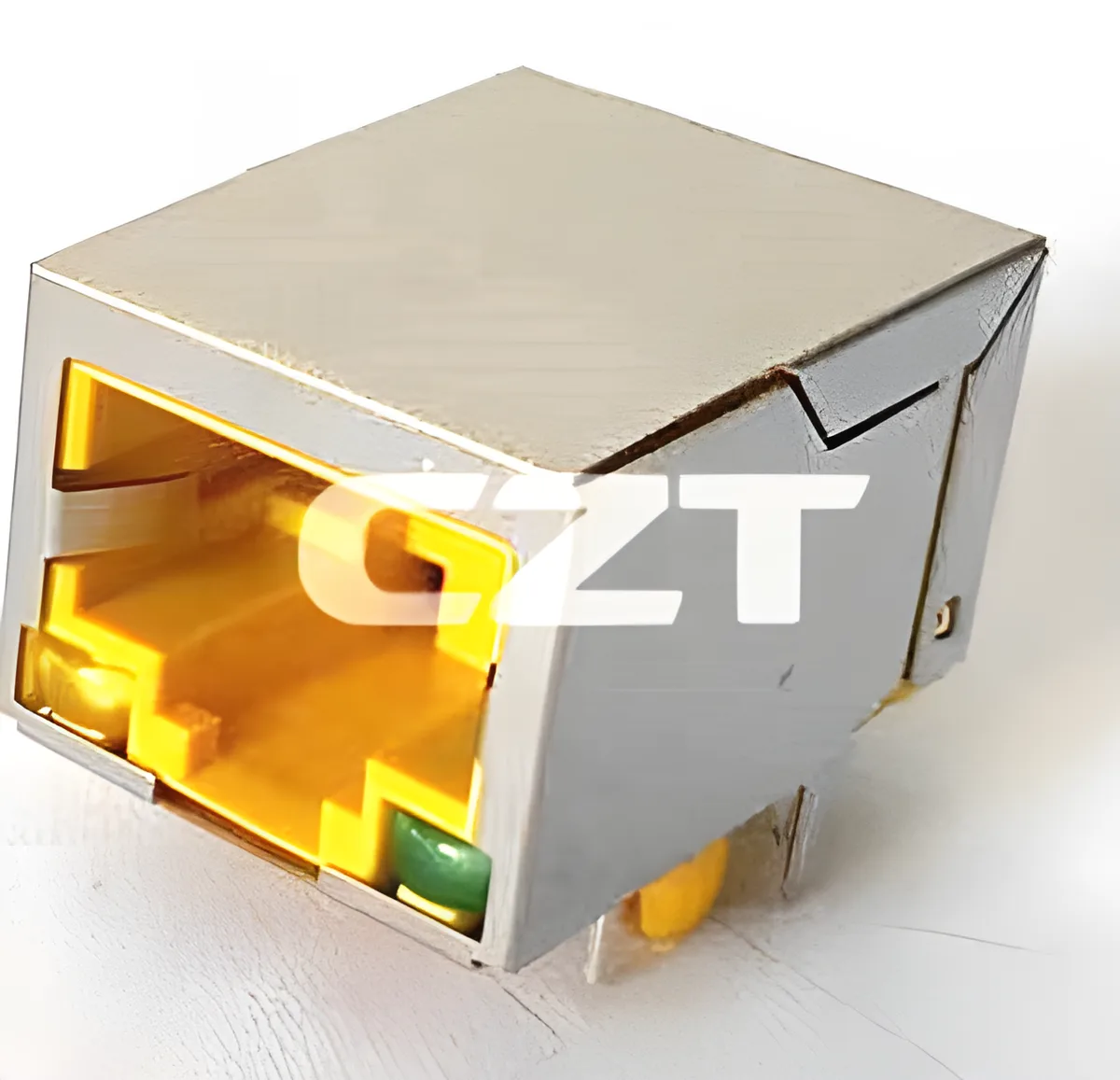
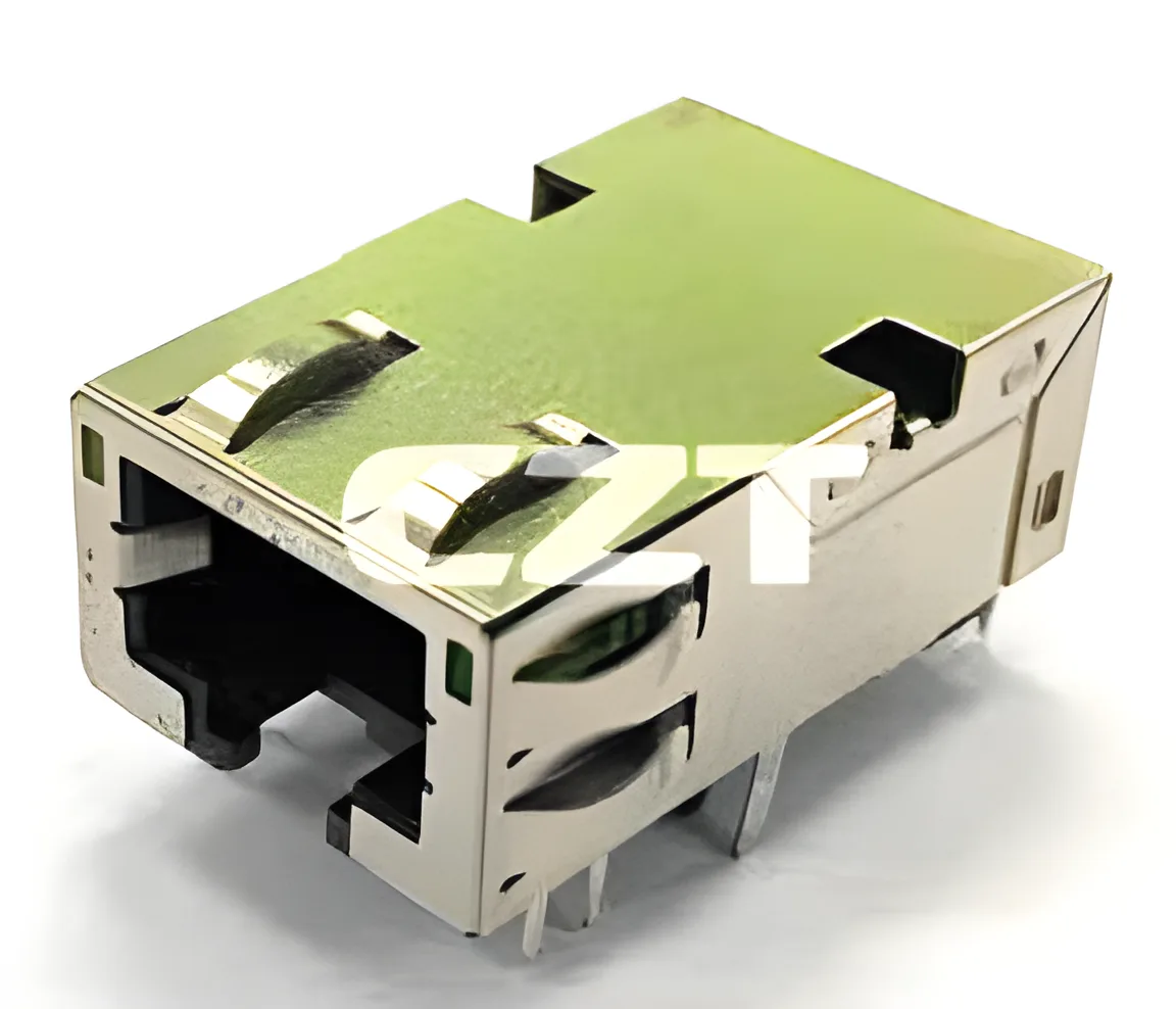
Review RJ45 contact geometry and mating depth as a controlled mechanical interface between a specified jack and plug. A matching eight-position opening does not prove that the contacts engage as intended in the finished assembly.
For a candidate in the CZT integrated magnetics family, use the approved component drawing and an identified mating plug. The goal is to connect dimensional evidence with actual seating and contact engagement, without inventing an acceptance dimension from visual appearance.
Define the mating references
Identify the jack's mating face, contact region, latch feature and any stop surfaces shown on the drawing. On the plug, identify the corresponding dimensions and seating references. Keep the viewing direction consistent when transferring measurements into a comparison sheet.
Distinguish overall insertion travel from the position at which the interface is fully seated. A boot or enclosure feature can stop movement before the intended mating condition is reached, even though the plug appears almost installed.
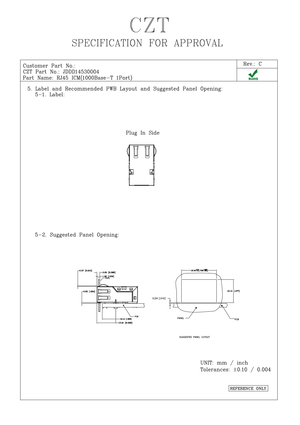
Figure 1. JDDD14530004: mating-interface geometry from the official manufacturer specification, PDF page 4. CZT source · Original PDF, page 4.
Inspect contact position without disturbing it
Choose an observation method that preserves the contact geometry. Pushing on a spring contact to make it easier to photograph can change the condition being measured. Document lighting, magnification and sample orientation so repeated images can be compared meaningfully.
Measure only dimensions that have a defined reference and acceptance basis. If the drawing omits a feature important to the application, request clarification rather than creating an unofficial production tolerance.
Build a geometry worksheet
| Interface feature | Record |
|---|---|
| Jack identity | Full model, drawing revision and sample batch |
| Mating plug | Part identification and dimensional reference |
| Seating | Defined stop and latch engagement condition |
| Contact position | Approved reference and measurement method |
| Assembly envelope | Panel, boot and cable interference checks |
| Functional correlation | Relevant continuity and mating observations |
Photographs support the worksheet but should not replace the dimensional references. Keep original images so an annotation cannot obscure the feature under review.
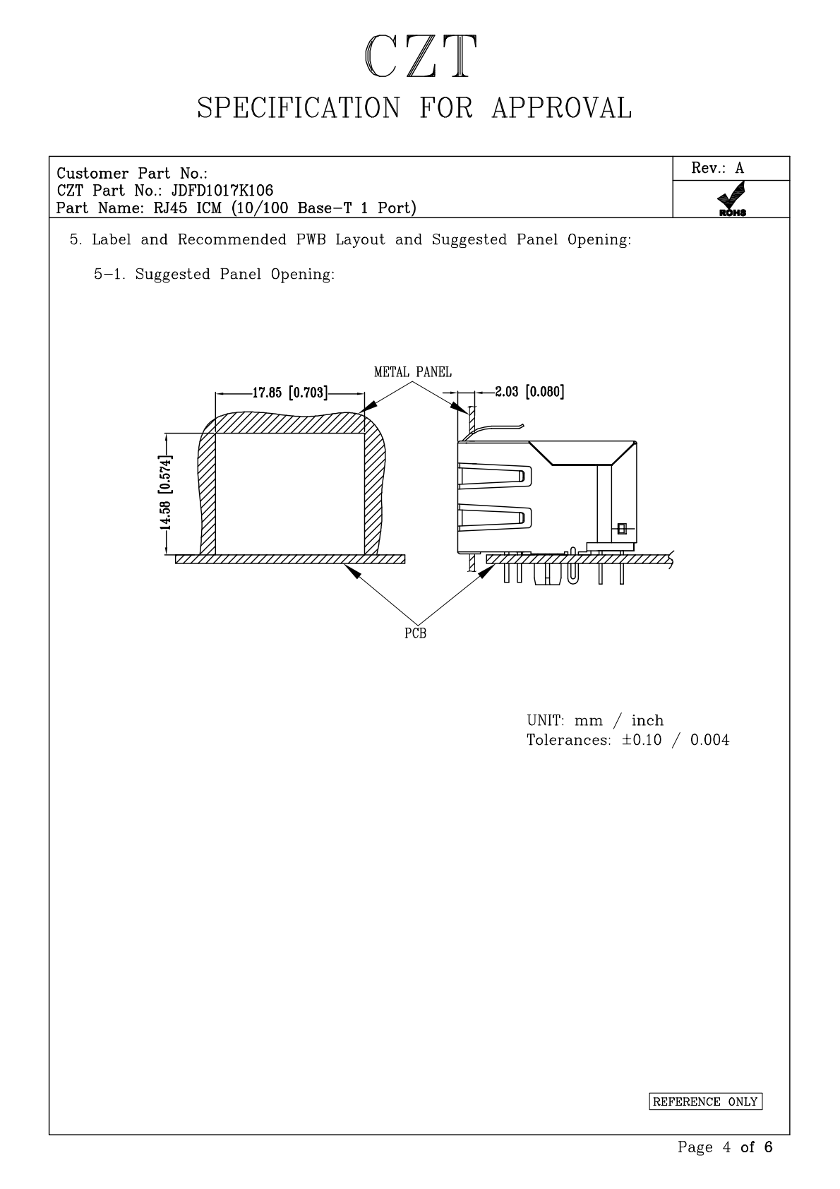
Figure 2. JDFD1017K106: mating-interface geometry from the official manufacturer specification, PDF page 4. CZT source · Original PDF, page 4.
Investigate incomplete engagement systematically
For a hypothetical assembly, an oversized cable boot could contact the panel before the plug reaches its intended seated position. The resulting electrical intermittence would require review of the assembly envelope, not an immediate conclusion that the jack contacts are defective.
Similarly, visible contact asymmetry should trigger a comparison with the approved geometry and additional inspection. It should not be corrected by hand and then treated as an acceptable production condition without an authorized procedure.
Link dimensional and functional evidence
After geometry review, evaluate mating, latching and electrical behavior with representative samples. Retain the accepted plug-jack combination and panel arrangement in the release record.
This approach helps distinguish a component dimensional issue from an enclosure or mating-accessory issue. It also creates a practical basis for reviewing future substitutions rather than relying on whether two connectors look similar in catalogue photographs.
Connect this review to CZT product information
Catalog references to discuss are listed below. Use the identifiers to request the current drawing and confirm the configuration required by your application.
| Catalog reference | Product information | Drawing record | Reference inquiry |
|---|---|---|---|
| JDGD14100001 | RJ45 ICM catalog-listed 1000BASE-T 1-port type, JDGD14100001 | Listed PDF | Ask about this reference |
| JDDD14530004 | RJ45 ICM catalog-listed 1000BASE-T 1-port type, JDDD14530004 | Listed PDF | Ask about this reference |
A catalog drawing reference is a starting document, not a substitute for reviewing its revision, options and suitability for the complete assembly.
Browse the relevant product family · View catalog resources
Discuss a drawing, sample or quotation
Share the part or family reference, current drawing revision, operating conditions and quantities. Include the specific checks described in this article so the inquiry identifies both the component and the evidence needed for your decision. Confirm sample availability and the proposed scope with the supplier.
Request a technical review or quotation
For broader context, read the related selection guide.