An RJ45 ICM inspection plan should distinguish visible signal joints, shield-retention joints and solder regions hidden by the component body. One top-view photograph cannot establish the quality of every connection.
Start with the actual mounting drawing for a candidate in the CZT integrated magnetics family. Map the joint locations onto the assembled PCB so inspection resources are directed at the places that carry electrical and mechanical responsibilities.
Classify the joints by function and visibility
Identify signal terminals separately from shield tabs and mechanical supports. Then mark which areas are visible after assembly and which are obscured. Consider the production sequence: a joint may be visible at one stage but concealed after an enclosure or neighboring component is installed.
This classification explains why an automated optical inspection program may need support from another inspection method. It also prevents a convenient visible joint from being treated as representative of an inaccessible one without evidence.
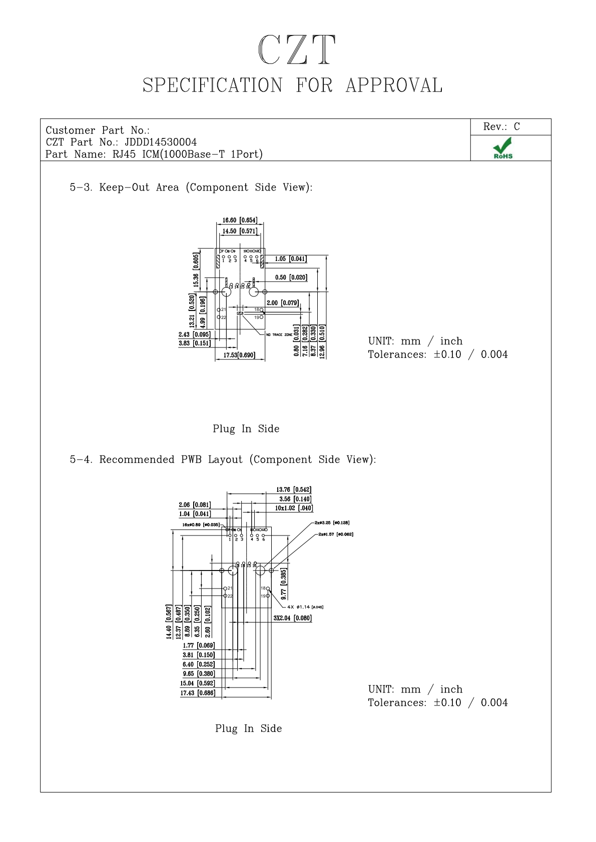
Figure 1. JDDD14530004: PCB layout and interface views from the official manufacturer specification, PDF page 5. CZT source · Original PDF, page 5.
Define a method for each critical region
Choose methods based on the construction and the project's accepted workmanship criteria. Depending on access and joint type, that may involve suitable optical views, process monitoring or a separately approved deeper examination of representative samples.
If a sectioned sample is used, identify exactly which joint and plane are examined. A section through an unrepresentative location can miss the feature under investigation.
Create a coverage matrix
| Joint region | Inspection decision |
|---|---|
| Signal terminals | Required view and electrical relevance |
| Shield or retention tabs | Solder coverage and mechanical function |
| Hidden interfaces | Chosen supplemental method and sample basis |
| Locating features | Seating and alignment check |
| Reworked region | Additional inspection after intervention |
For every row, assign an acceptance reference, inspection frequency and response to a suspect finding. Keep photographs of the actual approved construction rather than substituting generic connector images.

Figure 2. JDDD14530004 as pictured on its official manufacturer product page. CZT source · Original image.
Link solder findings to the load path
A shell tab may help transfer insertion and cable loads into the PCB. Its inspection priority therefore reflects more than whether the Ethernet signal currently passes. Review the intended enclosure support and connector retention arrangement alongside the solder requirements.
A hypothetical assembly can pass a continuity check while having inadequate attachment at a mechanical retention feature. Electrical function alone would not detect that assembly weakness.
Use failures to improve coverage
When a defect escapes inspection, record how it became visible and whether the original method could realistically have detected it. Update the inspection view, process control or sampling decision based on that evidence.
The final plan should show that every important connection has an intentional inspection route. It should not claim that an inaccessible joint is satisfactory simply because the automated system reported no visible defect elsewhere on the connector.
Connect this review to CZT product information
Start with the relevant CZT product family and provide the original interface reference or controlled drawing. Ask which configurations and supporting documents are available for the task described here. Confirm the mating arrangement, required features and project conditions before choosing an orderable part.
Browse the relevant product family · View catalog resources
Discuss a drawing, sample or quotation
Share the part or family reference, current drawing revision, operating conditions and quantities. Include the specific checks described in this article so the inquiry identifies both the component and the evidence needed for your decision. Confirm sample availability and the proposed scope with the supplier.
Request a technical review or quotation
For broader context, read the related selection guide.