Investigate EMI leakage around an SFP opening by linking measured emissions to the cage, panel and PCB grounding geometry. A metal cage is one part of the containment path; its presence does not guarantee the completed equipment's EMC result. Preserve the baseline setup, then change one physical interface at a time.

Figure 1. CZT SFP+ cage exterior shows opening and shell features relevant to locating the physical containment and grounding interfaces. CZT source · Original image.
Establish a repeatable emission condition
Record the operating ports, module identities, traffic or test mode, connected cables and enclosure state. Keep the measurement setup and software configuration stable during comparisons. A different active port or cable route can change the observation before any cage detail is modified.
Locate the relevant opening or seam with appropriate laboratory methods. Distinguish a local diagnostic observation from a formal whole-equipment result. A near-field change can guide investigation without proving that the product meets its emissions requirement.
Trace the physical contact path
Inspect where the cage contacts the panel and where it connects to the PCB or chassis ground structure. Include surface coatings, panel alignment and mechanical seating. Look for contact features displaced, obstructed or outside their intended operating position.
TE's SFP+ cage EMI and thermal paper discusses containment and cooling together. Any proposed remedy must be evaluated in the actual construction rather than assigned the performance of another manufacturer's design.
Use a controlled troubleshooting checklist
| Suspected interface | Evidence to inspect |
|---|---|
| Cage to front panel | Contact location, seating and surface condition |
| Cage to PCB | Mounting integrity and grounding geometry |
| Panel seams | Assembly consistency and gap changes |
| Port occupancy | Module, cable and unused-port configuration |
| Temporary modification | Exact location and comparison-test record |
Temporary conductive tape or another diagnostic measure can help locate a path, but it is not automatically a production solution. Its durability, assembly control and effect on cooling would need separate review.
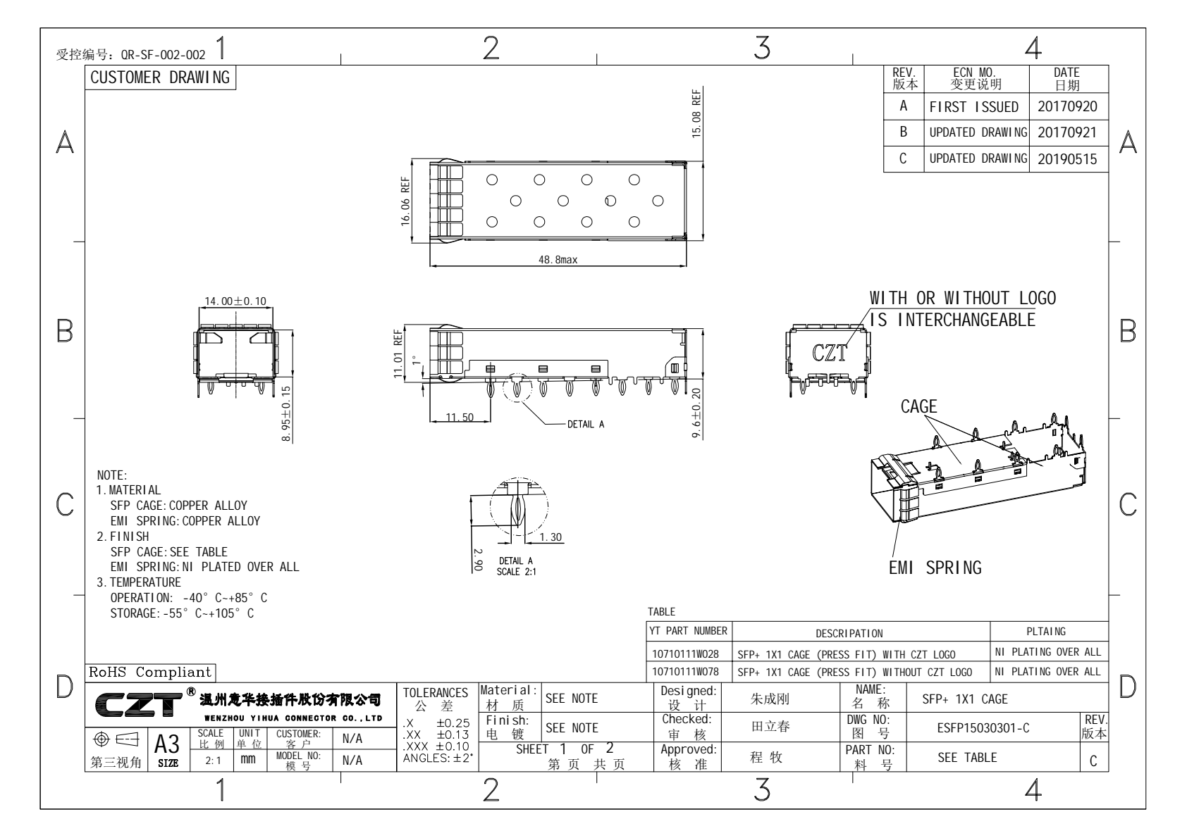
Figure 2. Official CZT cage drawing provides installation geometry for checking panel and board relationships during an EMI investigation; it is not an EMC report. CZT source · Original PDF, page 1.
Verify the final construction
After identifying a likely mechanism, test the production-intent correction under the original operating setup. Inspect neighboring ports and thermal consequences. A change that closes an opening may alter ventilation or service access, so the review should follow those interactions.
CZT's pluggable-I/O family provides cage references for an interface discussion. The catalog does not prove whole-equipment compliance or a specific shielding value. Ask for the relevant drawing and any available part-specific evidence while keeping formal equipment acceptance with the system test plan.
Record all temporary changes on a marked photograph and return the setup to baseline where practical to check repeatability. Several untracked modifications can produce a better result while leaving uncertainty over which change actually addressed the observed path.
A useful report distinguishes the baseline emission, diagnostic observations, proposed mechanism and final verification. Record unresolved paths instead of labeling the entire cage defective from one local measurement. That gives the next design revision a specific physical problem to solve and a reproducible comparison for confirming improvement.
Connect this review to CZT product information
Start with the relevant CZT product family and provide the original interface reference or controlled drawing. Ask which configurations and supporting documents are available for the task described here. Confirm the mating arrangement, required features and project conditions before choosing an orderable part.
Browse the relevant product family · View catalog resources
Discuss a drawing, sample or quotation
Share the part or family reference, current drawing revision, operating conditions and quantities. Include the specific checks described in this article so the inquiry identifies both the component and the evidence needed for your decision. Confirm sample availability and the proposed scope with the supplier.
Request a technical review or quotation
For broader context, read the related selection guide.