Quick Answer
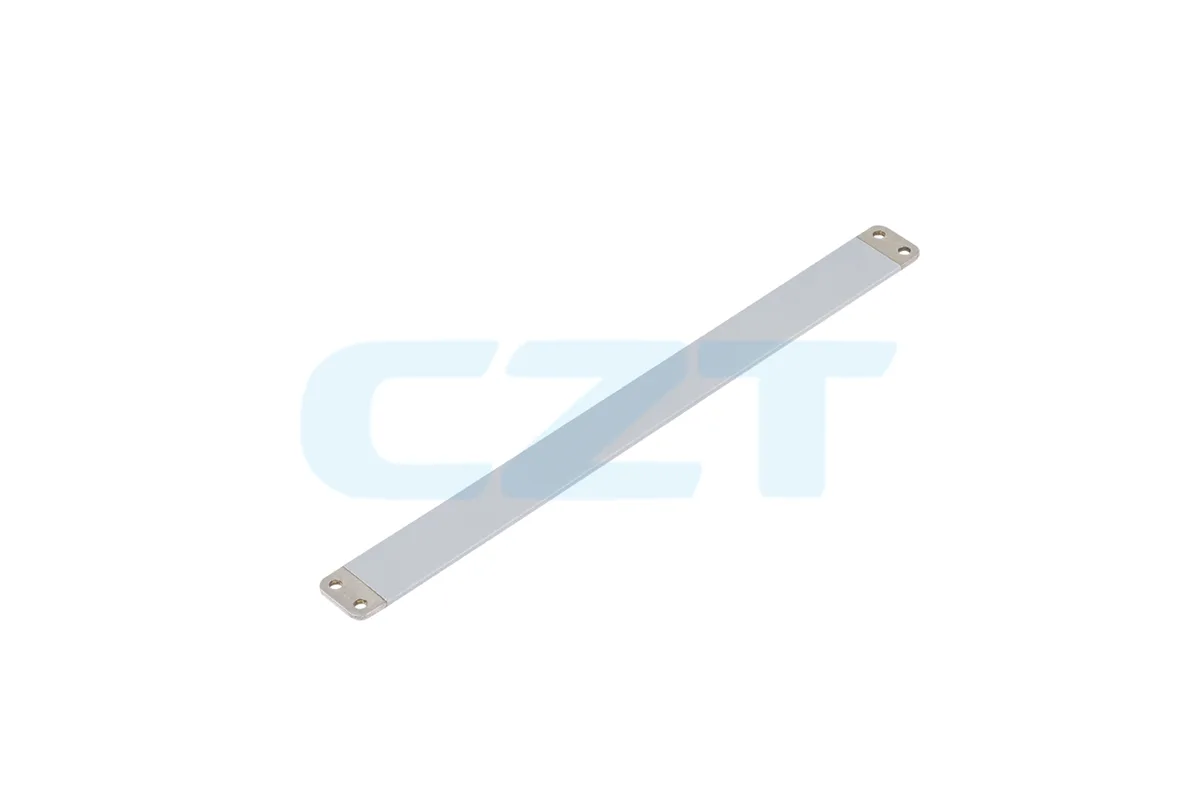
A sheet metal busbar is a flat electrical conductor blanked from copper or aluminum sheet, then formed and plated to distribute high current inside power electronics, battery systems, and switchgear. Key design decisions are material grade (C11000 copper at 101% IACS vs. 1050 aluminum at 61% IACS), sheet thickness (0.5–6.0 mm), bend radius (minimum 1t for annealed copper), and surface finish (tin for general use, nickel for high-temperature joints). Progressive-die stamping is the most cost-effective process for volumes above ~5,000 pieces; CNC punching and laser cutting serve lower volumes and thicker stock.
Looking for a busbar fabrication partner? Request a busbar quote — we supply stamped and CNC-formed busbars from prototype to high-volume production. Browse industrial connector products →
Introduction
Every high-current electrical system needs a way to move power between components. Cables work for point-to-point connections, but when you need to distribute current across multiple tap points inside a compact enclosure — an EV battery pack, a power distribution unit (PDU), or an energy storage inverter — a busbar is the standard solution.
Among the many busbar types, sheet metal busbars are the most widely manufactured. They start as flat copper or aluminum sheet, get blanked or punched into a 2D profile, formed into a 3D shape through bending, and finished with a conductive plating. The result is a rigid, high-current conductor with precisely located mounting holes, controlled impedance, and a corrosion-resistant surface.
This guide covers the full fabrication chain — from raw material selection through stamping, bending, plating, and quality inspection — with the specific design rules engineers need to get a busbar from concept to production.

Sheet Metal Busbar Materials
Material selection is the first decision and it constrains everything downstream: cross-sectional area for a given current, formability limits, plating compatibility, and cost.
Copper Alloys for Busbars
| Property | C11000 (ETP) | C10200 (OFE) | C26000 (Brass) |
|---|---|---|---|
| Conductivity (% IACS) | 101 | 101 | 28 |
| Thermal conductivity (W/m·K) | 391 | 391 | 120 |
| Density (g/cm³) | 8.94 | 8.94 | 8.53 |
| Tensile strength, annealed (MPa) | 220–260 | 220–260 | 300–350 |
| Min bend radius (annealed, per t) | 1.0t | 1.0t | 1.0t |
| Typical use | Power busbars, general | High-purity, vacuum | Low-current signal busbars |
C11000 ETP (Electrolytic Tough Pitch) copper is the default busbar material. It offers 101% IACS conductivity, good formability in the annealed temper, and accepts tin, nickel, and silver plating without issue. Specify it unless you have a specific reason not to.
C10200 OFE (Oxygen-Free Electronic) copper has identical conductivity but lower oxygen content (<10 ppm vs. ~200–400 ppm for ETP). It is specified for hydrogen-atmosphere brazing or vacuum applications where residual oxygen causes embrittlement. For stamped busbars with standard plating, OFE rarely offers a meaningful advantage over ETP.
Aluminum Alloys for Busbars
| Property | 1050-H14 | 1070-H14 | 6101-T6 |
|---|---|---|---|
| Conductivity (% IACS) | 61 | 62 | 56 |
| Thermal conductivity (W/m·K) | 229 | 234 | 218 |
| Density (g/cm³) | 2.71 | 2.71 | 2.70 |
| Tensile strength (MPa) | 105–145 | 95–130 | 200–240 |
| Min bend radius (per t) | 1.0t | 1.0t | 2.0–3.0t |
| Typical use | Formed busbars, weight-sensitive | High-conductivity bus | Structural busbars, bolt-on |
1050 and 1070 aluminum offer the best conductivity-to-formability ratio for stamped and bent busbars. They bend tightly (1t radius, annealed) and stamp cleanly, but their low tensile strength means mounting features must be reinforced or supported.
6101-T6 has higher strength and is common in extruded busbar profiles, but its reduced ductility makes tight bends difficult. It is better suited for straight or single-bend busbars where mechanical rigidity matters more than complex forming.
For a deeper dive into the copper-versus-aluminum decision, see Busbar Material: Copper vs. Aluminum.
Current Capacity Reference
The cross-sectional area required for a given current depends on the allowable temperature rise. The table below provides conservative ratings at a 30 K rise above 40 °C ambient for bare (unenclosed) copper busbars.
| Cross-section (mm²) | Sheet dimensions (mm) | DC current at 30 K rise (A) |
|---|---|---|
| 10 | 10 × 1.0 | 80–100 |
| 25 | 12.5 × 2.0 | 150–190 |
| 50 | 25 × 2.0 | 260–320 |
| 100 | 25 × 4.0 | 440–530 |
| 200 | 50 × 4.0 | 700–850 |
| 400 | 50 × 8.0 | 1,100–1,350 |
For aluminum, derate by approximately 38–40% or increase cross-sectional area by ~60% to match copper capacity. Actual ratings depend on enclosure, proximity to other conductors, and altitude — always validate with thermal simulation or testing for safety-critical applications.
Manufacturing Process
Sheet metal busbar fabrication follows a sequence: blank → punch → form → deburr → clean → plate → inspect. The specific equipment at each step depends on volume, material thickness, and geometry complexity.
1. Blanking and Punching
The process starts with flat sheet stock, typically supplied in coil for progressive-die operations or pre-cut sheets for CNC processing.
Progressive-die stamping is the highest-throughput method. A coil of sheet copper or aluminum feeds through a die set that performs multiple operations — blanking the outer profile, punching mounting holes, and sometimes forming bends — in a single press stroke cycle. Economical for volumes above 5,000–10,000 pieces per order and material thicknesses up to ~3 mm.
CNC turret punching uses a programmable punch press with interchangeable tooling. It handles thicker stock (up to ~6 mm copper), short runs, and rapid design iterations without dedicated die tooling. Per-piece cost is higher than stamping, but tooling investment is minimal.
Laser cutting offers the highest geometric flexibility — complex profiles, tight internal radii, and no tooling cost. It is practical for prototypes, very small batches, and designs with features too close together for punch tooling. Drawback: laser-cut edges on copper are rougher than punched edges and may need secondary deburring for plating adhesion.
| Process | Volume sweet spot | Max practical thickness (Cu) | Tooling cost | Lead time |
|---|---|---|---|---|
| Progressive-die stamping | >5,000 pcs | ~3 mm | $5,000–$30,000 | 4–8 weeks (tooling) |
| CNC turret punching | 50–5,000 pcs | ~6 mm | Minimal | 1–2 weeks |
| Laser cutting | 1–500 pcs | ~10 mm | None | 3–7 days |
2. Forming (Bending)
After blanking, flat busbar profiles are formed into their final 3D shape using press brakes or dedicated bending fixtures.
Critical design rules for bending:
- Minimum inside bend radius: 1× material thickness (1t) for annealed C11000 copper; 1.5t–2t for half-hard temper; 2–3t for 6101-T6 aluminum. Going below these limits causes outer-surface cracking.
- Bend orientation relative to grain: Bend lines perpendicular to the rolling direction whenever possible. Bending parallel to grain reduces ductility and may require a larger radius.
- Bend relief: Punched holes and slots near a bend line need a relief cutout to prevent tearing. Standard practice: relief width ≥ material thickness, relief depth extends at least 1 mm past the bend tangent line.
- Springback: Copper springs back 1–3° depending on temper and bend radius. Aluminum springs back 3–5°. Tooling must overbend to compensate. CNC press brakes with angle-measuring backgauges handle this automatically.
- Minimum flange length: The distance from the bend centerline to the nearest edge should be at least 2.5t + bend radius. Shorter flanges cannot be gripped by the press brake and will deform unpredictably.

3. Deburring and Edge Conditioning
Stamped and punched edges have a burr side (the die exit side) and a rollover side. Burrs must be removed before plating — sharp edges cause plating to thin or skip entirely at the edge, creating a corrosion initiation point.
Common deburring methods:
- Vibratory finishing (tumbling with ceramic media): handles high volumes, produces a uniform radius on all edges. Standard for stamped parts.
- Barrel deburring: similar to vibratory but uses a rotating barrel. Effective for smaller parts.
- Manual deburring: necessary for large or complex parts that cannot be tumbled. Uses rotary tools or hand files.
Target edge radius after deburring: 0.1–0.3 mm. This is sufficient for plating adhesion without significantly affecting the conductor cross-section.
4. Cleaning and Surface Preparation
Before plating, busbars must be chemically clean. The standard sequence:
- Alkaline soak clean — removes oils, stamping lubricant residue, and handling contamination.
- Acid activation — sulfuric or hydrochloric acid dip to remove surface oxides and expose fresh metal.
- Rinse — deionized water rinse between each step to prevent solution carryover.
Copper busbars that will be nickel- or silver-plated may receive a Wood's nickel strike (a thin, highly adherent nickel layer deposited from a chloride-heavy bath) before the main plating step. This ensures adhesion on any residual passive spots.
5. Plating and Surface Treatment
Surface treatment serves two purposes: it prevents base metal oxidation and it controls contact resistance at connection points.
| Finish | Thickness (µm) | Max operating temp | Contact resistance | Cost | Typical use |
|---|---|---|---|---|---|
| Tin (matte) | 3–8 | 130 °C | Low | $ | Bolted joints, general |
| Tin (bright) | 3–8 | 130 °C | Low | $ | Soldered terminations |
| Nickel | 5–15 | 300 °C | Medium | $$ | High-temp, solder barrier |
| Silver | 3–10 | 200 °C | Lowest | $$$$ | RF busbars, ultra-low-loss |
| Nickel + tin | 3–5 Ni / 3–8 Sn | 150 °C | Low | $$ | EV battery packs |
| Bare (passivated) | — | — | Higher, rising over time | — | Low-cost, non-critical |
Tin plating is the industry standard for most power busbars. It maintains low contact resistance over the busbar's service life and is compatible with both bolted and soldered connections. Specify matte tin for bolted joints (it resists tin whisker formation better than bright tin) and request a minimum thickness of 5 µm for long-term reliability.
Nickel plating is specified for busbars operating above 130 °C, or as a barrier layer under tin or silver to prevent copper diffusion into the surface layer at elevated temperatures. This nickel-then-tin stack is common in EV battery and energy storage busbar assemblies.
Selective plating — plating only the contact areas while leaving the body bare or passivated — reduces material cost for large busbars where only the bolt holes and terminations need protection. CZT supports selective plating through masking or post-plate stripping.
6. Inspection and Quality Control
Dimensional and electrical inspection ensures every busbar meets its drawing specifications.
| Parameter | Method | Typical tolerance |
|---|---|---|
| Overall length / width | CMM or optical measurement | ±0.1 mm (stamped), ±0.2 mm (laser-cut) |
| Hole position | CMM or pin-gauge fixture | ±0.05 mm (stamped), ±0.1 mm (CNC punched) |
| Hole diameter | Go/no-go gauges | ±0.05 mm |
| Bend angle | Digital protractor or fixture check | ±0.5° |
| Plating thickness | XRF (X-ray fluorescence) | Per spec ±20% |
| Plating adhesion | Tape-pull test (ASTM B571) | No peeling |
| Resistance | 4-wire micro-ohm measurement | Per design target |
| Visual / burr | 100% visual or automated optical | IPC-A-600 Class 2 or 3 |
For safety-critical applications — EV battery interconnects, UL-listed switchgear — CZT provides full PPAP (Production Part Approval Process) documentation including dimensional reports, material certs, and plating thickness logs.
Design Considerations
Hole Patterns and Hardware
Busbar mounting and connection holes must be sized for the fastener plus clearance, and positioned to meet creepage and clearance requirements per IEC 60664-1 or UL 508A.
Standard bolt sizing for busbar connections:
| Bolt size | Hole diameter | Washer OD | Torque (Nm) | Approx. current per bolt (A) |
|---|---|---|---|---|
| M5 | 5.5 mm | 10 mm | 4–6 | 50–80 |
| M6 | 6.6 mm | 12 mm | 8–12 | 80–120 |
| M8 | 9.0 mm | 16 mm | 18–25 | 150–250 |
| M10 | 11.0 mm | 20 mm | 35–50 | 250–400 |
| M12 | 13.5 mm | 24 mm | 55–80 | 400–600 |
Always use a flat washer under the bolt head and nut to distribute clamping force across the plated surface. For applications subject to vibration, add a Belleville (disc spring) washer or Nord-Lock pair to maintain joint preload over thermal cycles.
Thermal Management
Busbars generate heat through I²R losses. In enclosed assemblies — battery packs, PDUs, inverter cabinets — this heat must be managed to prevent exceeding the plating's temperature limit and to avoid degrading adjacent insulation.
Design strategies:
- Increase width rather than thickness to maximize surface area for convective and radiative cooling. A 50 × 2 mm busbar dissipates heat more effectively than a 25 × 4 mm busbar with the same cross-section.
- Add thermal interface pads between the busbar and a heatsink or enclosure wall for conduction cooling in sealed assemblies.
- Use nickel plating (not tin) if the busbar surface will exceed 130 °C, since tin softens and loses clamping force at that temperature.
- Simulate thermal rise using FEA (ANSYS, COMSOL) for safety-critical designs. Analytical estimates are adequate for initial sizing but do not capture localized hot spots at bends or contact transitions.
Insulation and Creepage
Bare busbars in switchgear and battery packs require insulation to prevent arc faults and accidental contact. Common approaches:
- Heat-shrink tubing (polyolefin, fluoropolymer): applied after forming and plating. Available with adhesive lining for sealed applications. Rated to 600 V in most formulations.
- Epoxy powder coating: provides a robust, scratch-resistant insulation layer (0.2–0.5 mm). Applied electrostatically and cured at 180–200 °C. Selective masking keeps contact areas bare.
- Kapton (polyimide) tape wrapping: used in aerospace and high-temperature applications. Labor-intensive for complex geometries.
- Overmolding: injection-molded insulation (PA66, PBT) encapsulates the busbar except at connection points. Highest cost but best for vibration resistance and sealed environments.
Creepage and clearance distances between live busbars and grounded enclosures must comply with IEC 60664-1 (industrial) or IEC 60664-5 (low-voltage equipment). At 800 V DC — common in modern EV platforms — minimum clearance is 8 mm and creepage 12.5 mm for Pollution Degree 2 environments.
Applications
EV Battery Packs
Sheet metal busbars connect individual cells into series-parallel configurations inside battery modules and packs. Requirements:
- Thin profile (0.5–2.0 mm) to fit between cell terminals
- Laser welding or ultrasonic bonding zones (requires bare, unplated copper at the weld point)
- Nickel or nickel-tin plating for temperatures up to 150 °C
- Tight positional tolerances (±0.1 mm on hole patterns) to align with cell terminal spacing
CZT supplies cell-to-cell interconnect busbars and module-level distribution busbars for EV battery pack OEMs and Tier 1 suppliers.
Power Distribution Units (PDUs)
PDUs in EV and industrial applications use multiple formed busbars to route power from a main bus to fused output circuits. Busbars in this application are typically 2–4 mm copper, tin-plated, with multiple bends to navigate around fuse holders and relay modules.
Energy Storage Systems (ESS)
Grid-scale and commercial ESS cabinets rely on busbars to connect battery racks to inverters and DC disconnects. Cross-sections of 100–400 mm² are common. For inverter DC link connections, laminated busbars may be preferred over solid stamped busbars to minimize parasitic inductance. Stamped busbars remain the standard for battery-to-battery rack connections and main DC distribution.
Industrial Switchgear
Traditional busbar territory. Stamped and formed busbars distribute power inside panelboards, motor control centers, and busway systems rated from 100 A to several thousand amps. Standards compliance (UL 508A, IEC 61439) governs material, plating, and joint design.

Design-for-Manufacturing Checklist
Before submitting a busbar design for quotation, verify the following:
- Material and temper specified — e.g., C11000-H02 (half-hard) or C11000-O (annealed).
- Sheet thickness on drawing — do not leave it ambiguous; specify nominal ±tolerance.
- Bend radii ≥ minimum for material/temper — 1t for annealed Cu, 1.5–2t for half-hard Cu.
- Bend relief at holes near bend lines — relief width ≥ t, depth past bend tangent ≥ 1 mm.
- Grain direction noted if bends are tight — bends perpendicular to grain preferred.
- Hole sizes include tolerance — e.g., 6.6 +0.1/−0 mm for M6 clearance.
- Plating spec complete — material, thickness range, area (full or selective), standard (ASTM B545 for tin, ASTM B689 for nickel).
- Contact areas marked — identify surfaces that mate with other conductors; these may need tighter flatness or plating thickness requirements.
- Insulation specified — heat-shrink, powder coat, or overmold, with masking zones defined.
- Critical dimensions flagged — identify which tolerances are functional (hole position, bend angle) versus cosmetic.
FAQ
What is a sheet metal busbar?
A sheet metal busbar is a flat electrical conductor fabricated from copper or aluminum sheet stock using stamping, punching, or laser cutting, followed by forming (bending) and surface finishing. It distributes high current between components in power electronics, battery packs, and switchgear assemblies.
What thickness of copper sheet is used for busbars?
Most stamped copper busbars use sheet stock between 0.8 mm and 4.0 mm thick. Thinner gauges (0.5–0.8 mm) appear in low-current signal busbars and flexible interconnects. Thicker stock (4–6 mm) is used for high-current main distribution busbars but typically requires CNC punching rather than progressive-die stamping.
Should I choose copper or aluminum for a stamped busbar?
Copper (C11000 ETP) is the default for most power applications because its conductivity (101% IACS) allows the smallest cross-section. Aluminum (1050 or 6101-T6) is chosen when weight must be minimized — common in EV battery packs — or when material cost is the primary constraint. Aluminum busbars require roughly 60% more cross-sectional area to carry the same current as copper.
What is the minimum bend radius for a copper busbar?
For annealed C11000 copper sheet, the minimum inside bend radius is typically 1× the material thickness (1t) for stock up to 3 mm. Half-hard temper requires 1.5t–2t. Going below minimum bend radius causes cracking on the outer surface, which increases resistance and creates a failure initiation point.
What surface finish is best for busbar connections?
Tin plating (3–8 µm) is the most common finish for bolted busbar joints because it prevents copper oxidation and maintains low contact resistance. Nickel plating (5–15 µm) is preferred for high-temperature environments above 150 °C or where solder reflow is required. Silver plating offers the lowest contact resistance but is cost-prohibitive for most applications.
Can CZT fabricate custom sheet metal busbars?
Yes. CZT manufactures custom stamped and CNC-formed busbars in copper and aluminum, from single prototypes to volumes exceeding 100k pieces per month. Services include progressive-die stamping, CNC bending, tin/nickel/silver plating, and 100% dimensional inspection.
Related Reading
- What Is a Busbar? — Definitions, working principles, and busbar basics.
- Busbar Types: Copper, Aluminum, Laminated & More — Compare form factors and construction methods.
- Energy Storage Busbar Design Considerations — ESS-specific design, laminated busbars, and thermal management.
- Busbar Material: Copper vs. Aluminum — Detailed conductivity, cost, and weight trade-off analysis.