Quick Answer
Busbar design for energy storage systems (ESS) centers on five parameters: current density (typically 2-4 A/mm² for copper, derated at elevated temperatures), voltage class (determines creepage/clearance distances per IEC 60664-1), thermal rise (target ≤30K above ambient), inductance (laminated busbars minimize loop inductance for fast-switching SiC/GaN inverters), and connection method (bolted joints for serviceability, welding for lowest resistance). See the full design guide below.
Need custom busbars for your ESS project? Browse CZT busbar products — copper and aluminum, laminated and rigid, custom-formed to spec. Request a quote →
Introduction
The global energy storage market is on a steep growth curve. Analysts project installed capacity to exceed 1 TWh by 2030, driven by grid-scale batteries, commercial peak-shaving systems, and residential solar-plus-storage. Behind every one of those systems sits a component that rarely makes headlines but determines whether the system performs safely and efficiently: the busbar.
A busbar is the primary current-carrying conductor inside an energy storage system (ESS). It connects battery modules to inverters, links parallel cell strings, and routes high DC currents through power conversion stages. Get the busbar design wrong, and you face thermal runaway risks, voltage drop losses, and premature system failure. Get it right, and you unlock higher power density, lower losses, and longer service life.
This article walks through the critical design considerations for busbars in energy storage applications — from material selection and thermal management to safety standards and emerging trends.
Why Busbars Matter in Energy Storage Systems
In any ESS, electrical energy must travel from battery cells through multiple connection points before reaching the grid or load. Every connection introduces resistance, and resistance means heat and lost energy. Busbars minimize both.
Here is why busbars are preferred over cables in most ESS designs:
High current capacity. A single copper busbar can carry hundreds or thousands of amps continuously. ESS systems routinely operate at 200 A to 4,000 A depending on architecture. Busbars handle these currents with lower resistance per unit length than equivalent cable bundles.
Thermal management. Busbars offer a large surface-area-to-volume ratio, which helps dissipate heat through convection and conduction. This is critical in sealed battery cabinets where airflow is limited. For a deeper comparison, see our guide on busbar vs cable performance.
Space efficiency. Battery cabinets are tightly packed. Flat busbars stack neatly between modules, saving 30-50% of the routing space that round cables would require.
Reliability. Bolted or welded busbar joints provide gas-tight connections with stable contact resistance over decades. Cable lugs, by contrast, can loosen under thermal cycling.
Repeatability. CNC-formed busbars are manufactured to tight tolerances, ensuring every unit in a production run performs identically — a requirement for ESS manufacturers shipping thousands of systems per year.
Types of Busbars Used in Energy Storage
Not all busbars are the same. The right type depends on voltage, current, switching frequency, and mechanical constraints. Here are the four main categories used in ESS applications.
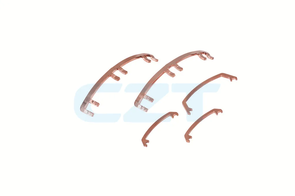
Rigid Copper Busbars
The simplest form: a solid copper bar, typically tin- or nickel-plated, bent to shape. Rigid busbars are cost-effective for short, straight runs between battery racks and DC disconnects.
Laminated Busbars
Multiple thin copper or aluminum layers separated by dielectric insulation, pressed into a single assembly. Laminated busbars are the gold standard for high-frequency power conversion stages in ESS inverters and battery management systems.
Flexible Busbars
Constructed from stacked thin copper foils or braided strands, flexible busbars absorb vibration and thermal expansion. They are commonly used to connect battery modules that may shift slightly during shipping or thermal cycling.
Custom-Formed Busbars
Complex 3D shapes produced by CNC bending, stamping, or a combination of both. Custom-formed busbars integrate mounting features, insulation barriers, and multiple connection points into a single part, reducing assembly time.
| Type | Pros | Cons | Typical ESS Application |
|---|---|---|---|
| Rigid copper | Low cost, simple, high conductivity | Limited flexibility, manual bending variation | DC main bus, battery rack interconnects |
| Laminated | Low inductance, compact, excellent thermal spread | Higher cost, longer lead time | Inverter DC link, BMS power stage |
| Flexible | Absorbs vibration and misalignment | Lower current density, higher resistance | Module-to-module connections, EV packs |
| Custom-formed | Optimized for specific geometry, integrated features | Tooling cost, design iteration required | Full system power distribution |
Laminated Busbars for ESS: Why They Dominate Power Conversion
Laminated busbars deserve special attention because they solve several problems at once in energy storage power electronics.
Low inductance. In a laminated busbar, the forward and return current paths are separated by only a thin dielectric layer (typically 0.1-0.25 mm). The opposing currents create magnetic fields that largely cancel each other, reducing parasitic inductance to as low as 5-20 nH. Low inductance means lower voltage spikes during switching events — critical for protecting IGBTs and SiC MOSFETs in ESS inverters.
Compact form factor. A laminated busbar replaces what would otherwise be a tangle of cables and discrete bus bars. A single laminated assembly can integrate the DC+, DC-, midpoint, and auxiliary power connections in a package just 3-5 mm thick.
Thermal performance. The large, flat surface area of a laminated busbar acts as a built-in heat spreader. Heat generated at connection points distributes across the full laminate area rather than concentrating at a single spot.
EMI reduction. The field-canceling geometry of laminated busbars significantly reduces electromagnetic interference, which helps ESS systems pass conducted emissions testing under FCC Part 15 and CISPR 11.

For energy storage applications, CZT manufactures laminated busbars with voltage ratings up to 1,500 VDC and current ratings exceeding 3,000 A. View our energy storage busbar product line for specifications.
Insulation Material Comparison
| Material | Dielectric Strength (kV/mm) | Max Temperature (°C) | UL 94 Rating | Relative Cost | Best For |
|---|---|---|---|---|---|
| Kapton (Polyimide) | 118 | 400 | V-0 | High | High-voltage ESS, aerospace |
| Nomex (Aramid) | 16 | 220 | V-0 | Medium | General ESS, automotive |
| Epoxy Powder Coat | 20 | 150 | V-0 | Low | Low-voltage, cost-sensitive |
| FR4 (Glass Epoxy) | 20 | 130 | V-0 | Medium | PCB-integrated busbars |
| DAP (Diallyl Phthalate) | 16 | 200 | V-0 | Medium-High | High-temperature industrial |
Key Design Parameters for Energy Storage Busbars
Designing a busbar for an ESS is not simply a matter of choosing a copper bar thick enough to carry the current. Several interrelated parameters must be balanced.
Current Rating
The continuous current rating depends on the conductor cross-section, material resistivity, and allowable temperature rise. For copper busbars at 20 degrees C, resistivity is 1.72 x 10^-8 ohm-m. A common design target is 2-4 A/mm^2 for enclosed ESS cabinets with natural convection cooling.
Busbar Sizing Formula
The minimum cross-sectional area for a copper busbar is:
A = I / J
Where:
- A = required cross-sectional area (mm²)
- I = rated current (A)
- J = allowable current density (A/mm²)
For copper busbars at 30°C ambient with ≤30K temperature rise, typical current density values are:
| Busbar Configuration | Current Density (A/mm²) |
|---|---|
| Single bar, free air convection | 2.0 - 3.0 |
| Multiple bars, stacked with gaps | 1.5 - 2.5 |
| Laminated busbar (enclosed) | 1.5 - 2.0 |
| Forced-air cooled | 3.0 - 5.0 |
Example: A 500A busbar in free air requires a minimum cross-section of 500 / 2.5 = 200 mm², equivalent to a 40 mm × 5 mm bar. In practice, derate by 20% for ambient temperatures above 40°C.
Voltage Drop Calculation
Voltage drop across a busbar is:
ΔV = I × R = I × (ρ × L) / A
Where:
- ρ = resistivity of copper at operating temperature (0.0175 Ω·mm²/m at 20°C, rising ~0.4% per °C)
- L = busbar length (m)
- A = cross-sectional area (mm²)
Example: A 500A, 300 mm long copper busbar with 200 mm² cross-section at 70°C:
- ρ at 70°C = 0.0175 × (1 + 0.004 × 50) = 0.021 Ω·mm²/m
- ΔV = 500 × (0.021 × 0.3) / 200 = 15.75 mV
For 800V ESS, this is negligible. For 48V residential systems, busbar voltage drop can become significant — keep total drop below 1% of system voltage.
Voltage Class
ESS voltage classes range from 48 V (residential) to 1,500 V (utility-scale). Higher voltages demand greater creepage and clearance distances between conductors, thicker insulation, and more rigorous testing.
Thermal Rise Limits
Most standards limit busbar temperature rise to 55-65 K above ambient. For an ESS operating in a 40 degrees C environment, that means the busbar surface temperature must stay below 95-105 degrees C. Exceeding this degrades insulation life and risks thermal runaway in adjacent battery cells.
Creepage and Clearance Distances
IEC 61439-1 and UL 508A define minimum distances between live conductors based on voltage, pollution degree, and insulation type. For a 1,000 VDC busbar in a pollution degree 2 environment, minimum clearance is typically 10-14 mm.
Material Selection: Copper vs. Aluminum
| Parameter | Copper (C110) | Aluminum (6101-T6) |
|---|---|---|
| Conductivity (% IACS) | 101 | 56 |
| Density (g/cm^3) | 8.94 | 2.70 |
| Tensile strength (MPa) | 220 | 200 |
| Cost per kg (relative) | 1.0x | 0.35x |
| Cost per amp-meter | 1.0x | 0.85x |
| Corrosion resistance | Good (with plating) | Requires anodizing or plating |
Copper dominates ESS busbar design because its higher conductivity allows smaller cross-sections, saving space in tight battery cabinets. Aluminum is used in cost-sensitive, high-volume applications where weight matters — such as EV battery packs.
Thermal Management in Busbar Design
Heat is the enemy of every energy storage system. Busbars generate heat through I^2R losses, and that heat must be managed to protect both the busbar and surrounding components.
Calculating Heat Generation
For a copper busbar carrying 500 A with a resistance of 0.1 milliohm, the power dissipated is:
P = I^2 x R = 500^2 x 0.0001 = 25 W
That 25 W must be dissipated through the busbar surface. In an enclosed cabinet, this is not trivial.
Thermal Simulation
Modern busbar design relies on finite element analysis (FEA) to predict temperature distribution. Simulation reveals hot spots at connection points, bends, and areas with reduced cross-section. CZT uses thermal simulation on every custom busbar project to validate designs before prototyping.
Cooling Strategies
- Natural convection. Sufficient for busbars under 200 A in open-air installations. Surface emissivity matters — black-anodized or painted surfaces radiate 3-5x more heat than bare copper.
- Forced air cooling. Fans directed across busbar surfaces can double the heat dissipation rate. Common in commercial ESS cabinets.
- Conduction cooling. Mounting busbars to aluminum heat sinks or cold plates transfers heat to a larger thermal mass. Used in high-density EV battery packs.
- Liquid cooling. For extreme current densities (above 10 A/mm^2), hollow busbars with internal coolant channels provide the highest thermal performance.
Derating
Busbars must be derated when operating at elevated ambient temperatures or in enclosed spaces with limited airflow. A typical derating curve reduces the current rating by 1-2% for every degree C above 35 degrees C ambient.
Connection Methods for ESS Busbars
The connection between a busbar and its mating component — a battery terminal, inverter stud, or fuse holder — is often the weakest link in the power path. Choosing the right connection method is essential.
Bolted Joints
The most common method. A bolt compresses the busbar against a flat mating surface, creating a gas-tight contact zone. Key considerations:
- Torque specification. Under-torqued joints have high contact resistance; over-torqued joints crack plating or deform the busbar. Typical values: M8 bolt = 20-25 Nm, M10 bolt = 40-50 Nm.
- Belleville washers. These spring washers maintain bolt tension as the joint thermally cycles, preventing loosening over time.
- Contact resistance target. A well-made bolted joint should have contact resistance below 10 micro-ohm.
Welded Connections
Laser welding or ultrasonic welding creates a permanent, zero-maintenance joint. Welded connections are preferred in sealed battery modules where access for retorquing is impossible. The trade-off is that welded joints cannot be disassembled for service.
Press-Fit Connections
A busbar tab is pressed into a plated through-hole on a PCB or busbar carrier. Press-fit connections are used in BMS power stages and low-current sensing circuits. They provide gas-tight contact without solder.
Spring Contacts
Spring-loaded contacts allow tool-free connection and disconnection. They are used in modular ESS designs where battery modules must be hot-swappable. Spring contacts typically handle lower currents (under 100 A per contact) but can be paralleled for higher ratings.
| Method | Current Range | Maintenance | Disassembly | Best For |
|---|---|---|---|---|
| Bolted | 50 - 5,000+ A | Periodic retorque | Yes | Main bus connections |
| Welded | 10 - 3,000 A | None | No | Sealed battery modules |
| Press-fit | 1 - 50 A | None | Difficult | BMS, PCB integration |
| Spring contact | 5 - 100 A per contact | None | Yes | Modular, hot-swap systems |
Safety Standards and Certifications
Energy storage systems operate at voltages and energy levels that can be lethal. Busbar design must comply with applicable safety standards.
UL 508A — Standard for industrial control panels. Covers busbar sizing, spacing, and temperature rise in enclosed assemblies. Required for ESS sold in North America.
IEC 61439 — International standard for low-voltage switchgear and controlgear assemblies. Defines temperature rise limits, dielectric strength, and short-circuit withstand for busbars.
UL 9540A — Test method for evaluating thermal runaway fire propagation in battery energy storage systems. While not a busbar-specific standard, busbar design directly affects thermal runaway propagation paths. Proper insulation and thermal isolation of busbars can help contain cell-level failures.
IEC 62477 — Safety requirements for power electronic converter systems. Relevant for busbars inside ESS inverters and DC-DC converters.
Insulation requirements. Busbar insulation in ESS applications must be rated for the system voltage plus a safety margin. Common insulation materials include Kapton (polyimide), Nomex (aramid), and epoxy powder coating. For 1,000 VDC systems, insulation must withstand a dielectric test of at least 2,500 VAC for 60 seconds.
CZT busbars are manufactured in ISO 9001-certified facilities and can be supplied with UL-recognized insulation materials and third-party test reports. Learn more about our capabilities for renewable energy solutions.
Busbar Design for Different ESS Architectures
The busbar requirements vary dramatically depending on the ESS voltage class and application.
Residential ESS (48 V)
Residential battery systems like those paired with rooftop solar typically operate at 48 VDC with currents of 100-200 A. Busbar design is relatively straightforward:
- Copper busbars, 3-5 mm thick, tin-plated
- Simple bent shapes connecting battery modules to a hybrid inverter
- Insulation: epoxy powder coat or heat-shrink tubing
- Bolted connections with M6-M8 hardware
Commercial ESS (400 V - 800 V)
Commercial and industrial systems operate at higher voltages to reduce current and cable costs. Busbar design becomes more demanding:
- Laminated busbars for the inverter DC link stage
- Creepage distances of 8-12 mm between polarities
- Rigid busbars with formed insulation barriers between battery racks
- Current ratings of 200-1,000 A
- Touch-safe covers and IP2X finger protection
Utility-Scale ESS (1,000 V+)
Grid-scale battery installations push voltages to 1,000-1,500 VDC. Busbar design at this level requires:
- Reinforced insulation rated for 1,500 VDC working voltage
- Creepage distances of 14-20 mm
- Short-circuit withstand ratings of 20-65 kA for 1 second
- Laminated busbars in the power conversion system (PCS)
- Custom-formed busbars connecting battery racks to DC combiners
EV Battery Packs
Electric vehicle battery packs present unique constraints: weight sensitivity, vibration, and extreme space limitations. Busbar design for EV packs typically uses:
- Aluminum busbars to reduce weight (30-40% lighter than copper at equivalent ampacity)
- Flexible busbars or foil stacks for cell-to-cell connections
- Laser-welded joints for permanent, vibration-resistant connections
- Nickel-plated surfaces for compatibility with aluminum cell terminals
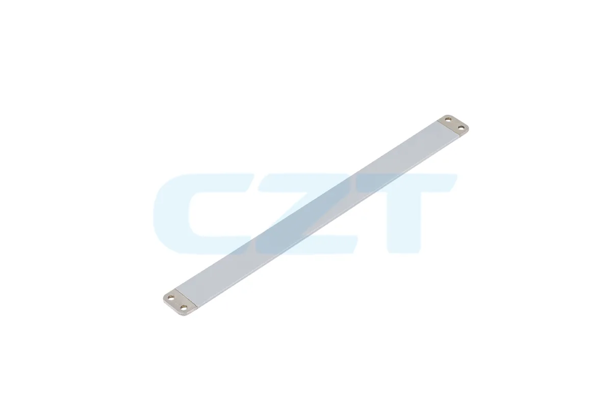
Custom Busbar Manufacturing
Off-the-shelf busbars rarely meet the exact requirements of a specific ESS design. Custom manufacturing is the norm in this industry.
CNC Bending
Computer-controlled bending machines form copper or aluminum bars into precise 3D shapes with tolerances of plus or minus 0.1 mm. CNC bending eliminates the variability of manual forming and ensures every part in a production run is identical.
Stamping
For high-volume production (10,000+ pieces per year), progressive die stamping is more cost-effective than CNC bending. Stamped busbars can integrate complex features like mounting holes, alignment tabs, and fuse clips in a single operation.
Plating Options
| Plating | Thickness | Purpose | Cost |
|---|---|---|---|
| Tin (Sn) | 3-8 micron | General corrosion protection, solderability | Low |
| Nickel (Ni) | 3-5 micron | High-temperature resistance, aluminum compatibility | Medium |
| Silver (Ag) | 3-10 micron | Lowest contact resistance, high-frequency performance | High |
| Nickel + Gold | 1-3 micron Au over Ni | Connector contacts, extreme reliability | Highest |
Prototyping Process
CZT offers a streamlined prototyping workflow for ESS busbar projects:
- Design review — Our engineers review your 3D model or schematic and provide DFM feedback within 48 hours.
- Prototype fabrication — First articles produced via CNC bending in 5-7 business days.
- Testing — Resistance measurement, hi-pot testing, and dimensional inspection per your specification.
- Iteration — Design revisions incorporated and new samples shipped within 3-5 business days.
- Production release — Tooling for stamping (if applicable) and transition to volume manufacturing.
Future Trends in ESS Busbar Design
The energy storage industry is evolving rapidly, and busbar technology is evolving with it.
Higher system voltages. The industry is moving toward 1,500 VDC and beyond for utility-scale systems. This pushes busbar insulation requirements higher and demands more rigorous partial discharge testing.
SiC and GaN integration. Wide-bandgap semiconductors switch faster and at higher temperatures than silicon IGBTs. Busbars connecting to SiC MOSFETs must have ultra-low inductance (under 10 nH) to prevent voltage overshoot. Laminated busbars with optimized layer stacking are essential.
Modular busbar systems. Standardized busbar modules that snap or bolt together are emerging for scalable ESS architectures. These reduce custom engineering time and allow field expansion of storage capacity.
Digital twins for thermal optimization. Manufacturers are building digital twin models of busbar assemblies that combine real-time sensor data with thermal simulation. This enables predictive maintenance — flagging joints that are degrading before they fail.
Additive manufacturing. 3D-printed copper busbars are moving from research labs to pilot production. Additive manufacturing enables internal cooling channels and topology-optimized shapes that are impossible with traditional bending or stamping.
Busbar Sizing Reference Table
Reference dimensions for copper busbars at ≤30K temperature rise in free air:
| Rated Current (A) | Min Cross-Section (mm²) | Typical Dimensions (mm) | Weight (kg/m) |
|---|---|---|---|
| 100 | 40 | 20 × 2 | 0.36 |
| 200 | 80 | 20 × 4 | 0.71 |
| 300 | 120 | 30 × 4 | 1.07 |
| 500 | 200 | 40 × 5 | 1.78 |
| 800 | 320 | 40 × 8 | 2.85 |
| 1,000 | 400 | 50 × 8 | 3.56 |
| 1,500 | 600 | 60 × 10 | 5.34 |
| 2,000 | 800 | 80 × 10 | 7.12 |
Values assume single copper bar, horizontal mounting, bare surface. For enclosed or stacked configurations, increase cross-section by 25-40%.
Frequently Asked Questions
What is a busbar in an energy storage system?
A busbar is a rigid metallic conductor — usually copper or aluminum — that distributes electrical current between battery modules, inverters, and other components inside an ESS. It serves as the main power highway, replacing bulky cable harnesses with a compact, low-resistance connection. For a full introduction, read our guide on what is a busbar.
Why are laminated busbars preferred in ESS inverters?
Laminated busbars place forward and return conductors in close proximity, which cancels magnetic fields and reduces parasitic inductance. Low inductance is critical in inverter DC link circuits because it limits voltage spikes during IGBT or SiC MOSFET switching events. Laminated busbars also offer superior thermal spreading and EMI performance compared to discrete bus bars.
How do I choose between copper and aluminum busbars?
Copper is the default choice for most ESS applications because its higher conductivity (101% IACS vs. 56% IACS for aluminum) allows smaller cross-sections, saving space in tight enclosures. Aluminum is preferred when weight is the primary constraint — such as in EV battery packs — or when material cost must be minimized for high-volume production.
What safety standards apply to ESS busbars?
The primary standards are UL 508A (industrial control panels), IEC 61439 (switchgear assemblies), and UL 9540A (ESS fire propagation testing). Busbar insulation materials should carry UL recognition, and finished assemblies should pass dielectric withstand testing at 2x working voltage plus 1,000 V.
Can CZT manufacture custom busbars for my ESS project?
Yes. CZT has over 30 years of experience manufacturing custom connectors and busbars. We support projects from single prototypes through high-volume production, with CNC bending, stamping, and multiple plating options. Our ISO 9001-certified facility serves ESS, solar inverter, and EV battery customers worldwide. Visit our energy storage busbar products page or request a quote to get started.
CZT designs and manufactures custom busbars for energy storage, solar inverters, and EV battery systems. From prototype to mass production, our engineering team partners with you at every stage. Request a Quote →