Introduction
Modern power electronics demand more from their interconnects than a simple copper bar can deliver. Switching frequencies are climbing, power densities are increasing, and the margin for parasitic inductance keeps shrinking. The laminated busbar was engineered to meet exactly these challenges.
A laminated busbar is a multi-layer power distribution conductor that sandwiches thin sheets of copper or aluminum between layers of dielectric insulation, then bonds them into a single rigid assembly. The result is a compact, low-inductance bus structure that has become the standard interconnect in inverters, battery energy storage systems, EV power modules, and data center UPS equipment.
If you are designing or sourcing power electronics assemblies, this guide covers everything you need to know — from construction and working principles to material choices, design rules, and real-world applications. For a broader overview of busbar fundamentals, see our companion article: What Is a Busbar?.
What Is a Laminated Busbar?
A laminated busbar — also called a laminated bus plate, power overlay, or planar bus — is a pre-engineered power distribution component made from multiple flat conductor layers separated by thin insulating films. The entire stack is laminated under heat and pressure to form a monolithic structure.

How It Differs from Traditional Busbars
A traditional busbar is typically a single solid bar of copper or aluminum. It works well for low-frequency power distribution in switchgear and panelboards. However, when switching frequencies exceed a few kilohertz — as they do in IGBT- and SiC-based inverters — a solid bar's parasitic inductance creates dangerous voltage spikes across the switching devices.
Laminated busbars solve this by placing the positive and negative (or multi-phase) conductors in close, parallel proximity with only a thin dielectric between them. This geometry causes the magnetic fields generated by opposing currents to cancel, slashing loop inductance to a fraction of what a traditional busbar or cable harness produces.
In short: a traditional busbar distributes power, while a laminated busbar distributes power and manages parasitic inductance, EMI, and voltage transients by design.
How Laminated Busbars Work
The performance advantages of a laminated busbar stem from basic electromagnetic principles. Understanding these helps engineers specify the right design for their application.
Low Inductance Through Field Cancellation
When two conductors carrying equal and opposite currents are placed in close parallel proximity, their magnetic fields oppose and largely cancel each other. In a laminated busbar, the DC+ and DC- layers are separated by an insulation film as thin as 0.1 mm to 0.25 mm. This tight spacing maximizes field cancellation and minimizes the loop inductance of the power circuit.
Typical stray inductance values for a well-designed laminated busbar range from 5 nH to 20 nH — compared to 50 nH to 200 nH or more for an equivalent cable or solid-bar connection. In a fast-switching inverter, that difference translates directly into lower voltage overshoot (V = L × di/dt) and reduced stress on semiconductor devices.
Controlled Impedance
Because the conductor geometry is fixed and repeatable, a laminated busbar presents a consistent, predictable impedance across its entire area. This uniformity ensures balanced current sharing among parallel switching devices — a critical requirement in high-power modules where multiple IGBTs or MOSFETs switch simultaneously.
Even Current Distribution
The wide, flat conductor geometry of a laminated busbar spreads current across a large cross-sectional area rather than concentrating it in a round wire. This reduces hot spots, lowers I²R losses, and improves the thermal profile of the entire power stage.
Key Advantages of Laminated Busbars
Laminated busbars outperform traditional interconnect methods in nearly every metric that matters for power electronics. The table below summarizes the comparison.
Laminated Busbar vs Traditional Busbar Comparison
| Parameter | Laminated Busbar | Traditional Solid Busbar | Cable Harness |
|---|---|---|---|
| Stray inductance | 5–20 nH (very low) | 50–150 nH | 100–300 nH |
| Voltage overshoot | Minimal | Moderate to high | High |
| Size / footprint | Compact, flat profile | Bulky | Requires bend radii and routing space |
| EMI performance | Excellent (field cancellation) | Poor | Poor |
| Current sharing | Uniform across parallel devices | Uneven without careful layout | Uneven |
| Thermal performance | Good (large surface area, even distribution) | Good | Limited |
| Reliability | High (no loose wires, pre-tested assembly) | High | Moderate (many termination points) |
| Assembly time | Fast (drop-in, bolt-down) | Moderate | Slow (cut, strip, crimp, route) |
| Customization | Fully custom geometry per application | Standard bar sizes | Standard wire gauges |
Summary of Advantages
Beyond the table, here are the practical benefits engineers value most:
- Reduced semiconductor stress. Lower inductance means lower voltage spikes, which allows designers to use devices with tighter voltage margins or extend device lifetime.
- Smaller snubber circuits. In some designs, the inductance is low enough to eliminate snubber capacitors entirely, saving cost and board space.
- Built-in insulation. The dielectric layers provide phase-to-phase and phase-to-ground insulation rated to the system voltage, eliminating the need for separate insulating barriers.
- Repeatable performance. Every laminated busbar off the production line has the same inductance, impedance, and thermal characteristics — unlike hand-assembled cable harnesses.
- Simplified assembly. A single laminated busbar replaces dozens of individual cables and terminations, cutting assembly time and reducing the risk of wiring errors.
For a deeper comparison of busbars and cables, see Busbar vs Cable: When to Use Busbars.
Materials and Construction
The performance of a laminated busbar depends heavily on the materials chosen for its conductor layers, insulation, and surface finish.
Conductor Materials
Copper (C110 ETP) is the default conductor material for laminated busbars. It offers the best combination of electrical conductivity (100% IACS), thermal conductivity, and mechanical strength. Most high-performance laminated busbars for inverters and ESS use copper exclusively.
Aluminum (6101-T6) is used when weight reduction is the priority — for example, in aerospace or certain EV applications. Aluminum has about 61% of copper's conductivity, so conductor layers must be thicker to carry the same current. Aluminum laminated busbars are less common but growing in adoption for weight-sensitive platforms.

Insulation Materials
The dielectric film between conductor layers is one of the most critical material choices. Common options include:
| Insulation Material | Thermal Class | Dielectric Strength | Key Properties |
|---|---|---|---|
| Nomex (aramid paper) | 220°C (Class H) | 20–40 kV/mm | Excellent thermal endurance, UL recognized |
| Kapton (polyimide film) | 260°C+ | 150–300 kV/mm | Superior dielectric strength, thin films possible |
| Epoxy prepreg | 130–180°C (Class B/F) | 15–25 kV/mm | Good adhesion, cost-effective for moderate temperatures |
| Mylar (PET film) | 130°C (Class B) | 150–300 kV/mm | Low cost, good for lower-temperature applications |
| DMD composite | 155–180°C (Class F) | 20–40 kV/mm | Combines mechanical strength with good dielectric performance |
For most power electronics applications operating above 100°C ambient, Nomex or Kapton is the preferred choice. Epoxy prepreg is common in lower-temperature industrial drives and UPS systems.
Plating Options
Conductor surfaces at terminal areas are plated to prevent oxidation and ensure low contact resistance at bolted joints. Standard options include:
- Tin plating — general-purpose, cost-effective, compatible with most solder and crimp terminations
- Nickel plating — preferred for high-temperature environments (above 150°C) and aluminum wire bonding interfaces
- Silver plating — lowest contact resistance, used in high-reliability aerospace and military power electronics
Design Considerations
Designing a laminated busbar is not a simple exercise in cutting copper to shape. Several interdependent parameters must be balanced to achieve optimal electrical, thermal, and mechanical performance.
Current Capacity
The continuous current rating of a laminated busbar depends on conductor material, thickness, width, and the allowable temperature rise. A common design rule for copper laminated busbars is 3–6 A/mm² of cross-sectional area at a 40°C temperature rise, though this varies with cooling conditions and duty cycle.
For high-current applications (above 1,000 A), multiple conductor layers may be connected in parallel within the laminate stack to increase total cross-section without increasing overall thickness proportionally.
Voltage Rating
The voltage rating is determined by the insulation material, its thickness, and the required creepage and clearance distances. A typical laminated busbar for a 1,000 V DC bus uses 0.2–0.5 mm of Nomex or Kapton per insulation layer, providing a dielectric withstand voltage of 2,500–5,000 V AC (hipot test level).
Designers must account for both working voltage and transient overvoltage conditions. IEC 61800-5-1 and UL 508C provide guidance on insulation coordination for power drive systems.
Thermal Management
Heat generated by I²R losses must be dissipated without exceeding the insulation material's thermal class. Key thermal design strategies include:
- Increasing conductor thickness to reduce resistance
- Maximizing the exposed surface area of the busbar for convective and radiative cooling
- Adding thermal interface pads between the busbar and a heatsink or cold plate
- Incorporating cutouts or slots to direct airflow through the assembly
Creepage and Clearance Distances
For safety certification, the minimum distances between conductors of different polarity must meet the requirements of the applicable standard (IEC 61800-5-1, IEC 62477-1, or UL 508C). In a laminated busbar, creepage distance is measured along the surface of the insulation from one exposed conductor edge to the next.
Designers typically extend the insulation layer 3–10 mm beyond the conductor edges to achieve the required creepage distance for the rated voltage. At higher altitudes (above 2,000 m), clearance distances must be increased to account for reduced air dielectric strength.
Mechanical Integration
A laminated busbar must fit precisely within the power module or enclosure. Terminal hole patterns must align with semiconductor modules, capacitor banks, and output connectors. Mounting features — standoffs, inserts, and alignment pins — are often integrated directly into the busbar design to simplify assembly.
Applications
Laminated busbars are found wherever fast-switching power electronics require low-inductance, high-reliability interconnects. Below are the primary application areas.
EV and HEV Power Electronics
Electric vehicle traction inverters are one of the largest markets for laminated busbars. The busbar connects the DC link capacitor bank to the IGBT or SiC MOSFET power module, carrying hundreds of amps at 400 V or 800 V DC. Low inductance is essential to protect the switching devices during hard-switching transients at 10–20 kHz or higher.
Energy Storage Systems (ESS / BESS)
Battery energy storage systems use laminated busbars to interconnect battery module outputs, DC contactors, fuses, and the power conversion system (PCS). The busbar must handle high DC currents (often 500–2,000 A) while maintaining low inductance at the inverter interface. CZT manufactures custom laminated busbars for energy storage applications, designed to meet UL and IEC safety requirements.
For a detailed look at busbar design in ESS, see our article on energy storage busbar design considerations.
Solar Inverters
String inverters and central inverters for photovoltaic systems rely on laminated busbars to connect DC input stages, MPPT circuits, and H-bridge or three-level switching topologies. The busbar's low inductance reduces switching losses and EMI, improving inverter efficiency and enabling compliance with grid-tie EMC standards.
Uninterruptible Power Supplies (UPS)
Online double-conversion UPS systems use laminated busbars in both the rectifier and inverter stages. The busbar connects the DC bus capacitors to the switching devices and carries the full load current during normal operation and battery backup modes. Reliability and thermal performance are paramount in UPS applications where downtime is not an option.
Industrial Motor Drives
Variable frequency drives (VFDs) for industrial motors use laminated busbars to link the DC bus to the output inverter stage. As drive power ratings increase into the hundreds of kilowatts and megawatt range, laminated busbars become essential for managing inductance and ensuring even current distribution across parallel switching devices.
Data Center Power Distribution
High-density data center power architectures increasingly use laminated busbars in power shelves, battery backup units, and 48 V DC distribution systems. The compact form factor and low-loss characteristics of laminated busbars help maximize power density in space-constrained rack environments.
Laminated Busbar Specifications by Application
The table below shows typical specification ranges for laminated busbars across common application categories.
| Specification | EV Inverter | ESS / BESS | Solar Inverter | UPS | Industrial Drive |
|---|---|---|---|---|---|
| Rated voltage (DC) | 400–800 V | 600–1,500 V | 600–1,500 V | 400–800 V | 600–1,200 V |
| Rated current | 200–800 A | 500–2,000 A | 100–600 A | 100–500 A | 200–1,500 A |
| Stray inductance | < 10 nH | < 20 nH | < 15 nH | < 20 nH | < 20 nH |
| Conductor material | Copper (C110) | Copper (C110) | Copper or aluminum | Copper (C110) | Copper (C110) |
| Insulation material | Nomex / Kapton | Nomex / Kapton | Nomex / epoxy | Nomex / epoxy | Nomex / epoxy |
| Insulation class | H (220°C) | F–H (155–220°C) | B–F (130–155°C) | B–F (130–155°C) | F (155°C) |
| Plating | Nickel or tin | Tin or nickel | Tin | Tin | Tin |
| Hipot test voltage | 2,500–5,000 V AC | 3,000–6,000 V AC | 3,000–5,000 V AC | 2,500–4,000 V AC | 2,500–5,000 V AC |
| Typical layers | 2–4 | 2–6 | 2–4 | 2–4 | 2–4 |
These are representative ranges. Actual specifications depend on the system architecture, semiconductor technology, and applicable safety standards. CZT engineers work with customers to define the optimal specification for each project.
Manufacturing Process
Manufacturing a laminated busbar requires precision at every step. Here is the typical production flow.
Step 1: Design and Engineering
The process begins with a detailed electrical and mechanical design. Engineers define the conductor layout, layer stackup, insulation type, terminal locations, and mounting features based on the customer's circuit schematic and mechanical envelope. 3D CAD models and electrical simulations (inductance, current distribution, thermal) are used to validate the design before tooling.
Step 2: Material Preparation
Copper or aluminum sheets are sheared or laser-cut to the required conductor shapes. Insulation films are cut to match, with appropriate extensions beyond conductor edges to achieve creepage distance requirements. Terminal areas are masked for plating.
Step 3: Lamination
The conductor and insulation layers are stacked in the correct sequence, aligned using tooling pins, and placed in a lamination press. Heat (typically 150–200°C) and pressure (50–150 psi) are applied for a controlled duration to bond the layers into a monolithic assembly. The adhesive in the insulation film or prepreg cures during this step, creating a permanent bond.
Step 4: CNC Routing and Finishing
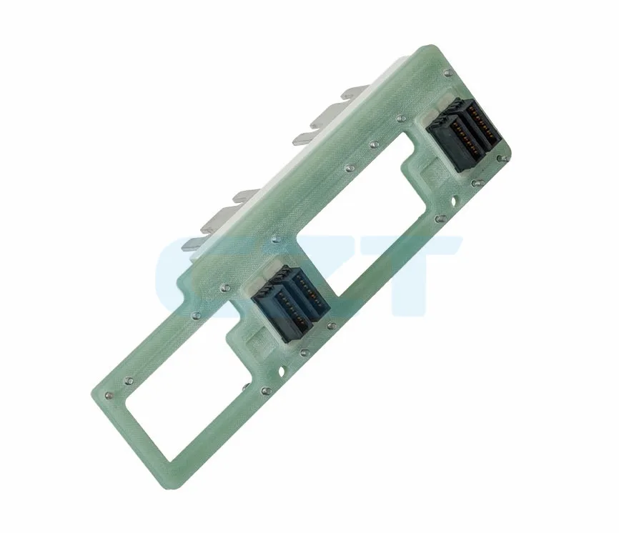
After lamination, the busbar assembly is CNC-routed to its final outline dimensions. Mounting holes, terminal holes, and alignment features are drilled or milled. Edges are deburred and inspected. Terminal pads are plated (tin, nickel, or silver) using selective plating or masking techniques.
Step 5: Testing and Inspection
Every laminated busbar undergoes a series of quality checks before shipment:
- Hipot (dielectric withstand) test — verifies insulation integrity at 2–3x the rated voltage
- Insulation resistance test — confirms resistance above 100 MΩ at 500 V or 1,000 V DC
- Dimensional inspection — checks critical dimensions against the drawing tolerances
- Visual inspection — examines for delamination, voids, plating defects, and edge quality
- Partial discharge test (for high-voltage applications) — detects micro-voids or insulation weaknesses
CZT maintains full in-house manufacturing capabilities — from stamping and lamination to CNC machining, plating, and electrical testing — ensuring traceability and quality control at every stage.
Frequently Asked Questions
What is the main advantage of a laminated busbar over a traditional busbar?
The primary advantage is dramatically lower parasitic inductance. A laminated busbar achieves stray inductance values of 5–20 nH, compared to 50–200 nH for a traditional solid busbar or cable harness. This low inductance reduces voltage overshoot during switching transients, protects semiconductor devices, and enables higher switching frequencies in power electronics.
What applications require laminated busbars?
Laminated busbars are required in any application where fast-switching power semiconductors (IGBTs, SiC MOSFETs, GaN devices) are used at significant power levels. The most common applications include EV traction inverters, battery energy storage systems, solar inverters, UPS systems, and industrial motor drives. Any design where parasitic inductance causes voltage spikes exceeding device safe operating limits benefits from a laminated busbar.
Can a laminated busbar replace cables in my power electronics design?
In most cases, yes. A single laminated busbar can replace an entire cable harness between the DC link capacitor and the power module, reducing assembly time, improving electrical performance, and increasing reliability. The trade-off is that laminated busbars are custom-designed for each application, so they require upfront engineering and tooling — unlike off-the-shelf cables.
How is a laminated busbar tested for quality?
Every laminated busbar is tested for dielectric withstand (hipot test), insulation resistance, and dimensional accuracy. High-reliability applications may also require partial discharge testing, thermal cycling, and vibration testing. CZT performs 100% hipot testing on all laminated busbars and provides full test reports with shipment.
How do I specify a laminated busbar for my project?
Start by defining the key electrical parameters: rated voltage, rated current, maximum switching frequency, and allowable stray inductance. Then provide the mechanical constraints: available envelope, terminal locations, and mounting features. CZT's engineering team can work from a circuit schematic and mechanical drawing to develop a complete laminated busbar design, including material selection, thermal analysis, and safety certification support.
Need a Custom Laminated Busbar?
CZT designs and manufactures laminated busbars for power electronics, energy storage, and renewable energy applications. From initial concept through prototyping, testing, and volume production, our engineering team delivers busbars optimized for your electrical, thermal, and mechanical requirements.
Related Products
- Busbar Solutions for Energy Storage — Laminated and solid copper busbars designed for battery energy storage systems, solar inverters, and high-current DC distribution.