Every piece of data traveling across a fiber optic network passes through an optical transceiver. These small, hot-pluggable modules are the bridge between electrical signals inside your networking equipment and the light pulses that race through fiber optic cables at near light speed.
If you work in data centers, telecom, or enterprise networking, understanding how transceivers work is essential. This guide covers everything from basic operating principles to the differences between SFP, SFP+, QSFP28, and other popular form factors. By the end, you will know exactly how to choose the right transceiver module for your application.
What Is an Optical Transceiver?
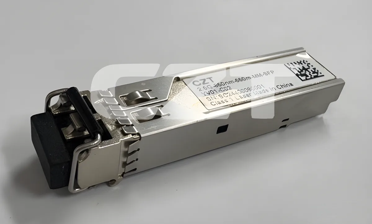
An optical transceiver is a compact electro-optical device that both transmits and receives data over fiber optic cable. The name itself is a combination of "transmitter" and "receiver," reflecting its dual function.
On the transmit side, the transceiver converts electrical signals from a network switch, router, or NIC into modulated light. On the receive side, it does the reverse — capturing incoming light from the fiber and converting it back into electrical signals the host device can process.
Modern transceivers are designed as hot-pluggable modules. That means you can insert or remove them from a compatible cage or slot without powering down the equipment. This design gives network engineers the flexibility to upgrade speeds, change wavelengths, or swap out failed modules in seconds.

Optical transceivers are standardized by multi-source agreements (MSAs). These industry agreements ensure that modules from different manufacturers are mechanically and electrically interchangeable, so a compliant SFP transceiver from one vendor will fit the same cage as one from another.
How Does an Optical Transceiver Work?
Understanding the internal workings of a transceiver module helps you troubleshoot link issues and make better purchasing decisions. The process breaks down into two signal paths: transmit (TX) and receive (RX).
Transmit Path (Electrical → Optical)
- The host device sends an electrical data signal to the transceiver through the gold-plated edge connector.
- A laser driver IC conditions and amplifies the signal.
- The driver modulates a laser diode (typically a VCSEL, FP, or DFB laser depending on wavelength and reach).
- The laser emits modulated light into the transmit fiber through a Transmitter Optical Sub-Assembly (TOSA).
For short-reach multimode applications (such as 850 nm SR links), a Vertical-Cavity Surface-Emitting Laser (VCSEL) is used. For long-reach single-mode links (1310 nm or 1550 nm), Distributed Feedback (DFB) lasers or Electro-absorption Modulated Lasers (EMLs) provide the higher power and narrower linewidth required.
Receive Path (Optical → Electrical)
- Incoming light from the fiber enters the Receiver Optical Sub-Assembly (ROSA).
- A photodetector (typically a PIN photodiode or APD) converts the light into a weak electrical current.
- A transimpedance amplifier (TIA) boosts the signal.
- A Clock and Data Recovery (CDR) circuit cleans up the signal and passes it to the host device.

The entire process happens in both directions simultaneously, enabling full-duplex communication over a pair of fibers or, in BiDi transceivers, over a single fiber using two different wavelengths.
Types of Optical Transceivers
The networking industry has developed multiple transceiver form factors over the years, each optimized for different data rates and port densities. Here is a comparison of the most common types.
| Form Factor | Data Rate | Typical Reach | Fiber Type | Common Use Case |
|---|---|---|---|---|
| SFP | 1 Gbps | Up to 120 km | SM / MM | Enterprise LAN, access networks |
| SFP+ | 10 Gbps | Up to 80 km | SM / MM | Data center ToR, metro transport |
| SFP28 | 25 Gbps | Up to 40 km | SM / MM | 5G fronthaul, leaf-spine fabric |
| XFP | 10 Gbps | Up to 80 km | SM | Legacy 10G DWDM, SONET/SDH |
| QSFP+ | 40 Gbps | Up to 40 km | SM / MM | Data center spine, core routing |
| QSFP28 | 100 Gbps | Up to 40 km | SM / MM | Hyperscale DC, 100G backbone |
| QSFP-DD | 400 Gbps | Up to 10 km | SM | Next-gen DC, 400G backbone |
| CFP / CFP2 / CFP4 | 100–400 Gbps | Up to 80 km | SM | Long-haul telecom, DWDM |
SFP (Small Form-factor Pluggable) remains the most widely deployed transceiver type globally. Its compact size and low cost make it the default choice for 1G access and aggregation links.
QSFP28 has become the workhorse of modern data centers, delivering 100 Gbps through four 25G lanes. It can also be broken out into four individual 25G SFP28 links using a DAC or AOC breakout cable.
QSFP-DD (Double Density) doubles the electrical lanes from four to eight, pushing aggregate bandwidth to 400 Gbps. It is backward compatible with QSFP28 modules, protecting your existing cage investments.
SFP vs SFP+ vs SFP28: What's the Difference?
These three form factors share the same physical dimensions and MSA-defined mechanical footprint, but they operate at very different speeds. Understanding the distinctions is critical when planning upgrades.
| Feature | SFP | SFP+ | SFP28 |
|---|---|---|---|
| Data Rate | 1 Gbps | 10 Gbps | 25 Gbps |
| Electrical Interface | 1 lane × 1.25 Gbaud | 1 lane × 10.3125 Gbaud | 1 lane × 25.78125 Gbaud |
| Typical Laser (SR) | VCSEL 850 nm | VCSEL 850 nm | VCSEL 850 nm |
| Typical Laser (LR) | DFB 1310 nm | DFB 1310 nm | DFB 1310 nm |
| Max Reach (SM) | 120 km (EZX) | 80 km (ER) | 40 km (ER) |
| Power Consumption | < 1 W | < 1.5 W | < 1.5 W |
| Backward Compatible | — | Accepts SFP | Accepts SFP / SFP+ |
Backward Compatibility
An SFP28 cage is electrically designed for 25G signaling, but it will accept and operate with an SFP+ (10G) or SFP (1G) module at the lower speed. This backward compatibility means you can deploy SFP28-equipped switches today and migrate from 10G to 25G on a port-by-port basis as your bandwidth needs grow.
However, the reverse is not true. Inserting an SFP28 module into an older SFP+ cage will not work at 25G because the host-side electrical interface cannot support the higher baud rate.
When to Use Each
- SFP: Best for 1G access ports, legacy equipment, and long-reach links where 1 Gbps is sufficient.
- SFP+: The standard for 10G server connections, storage networks, and metro Ethernet.
- SFP28: The go-to for 25G server-to-leaf links in modern data centers and 5G fronthaul using eCPRI.
Key Transceiver Specifications
When evaluating an optical transceiver for your network, these are the specifications that matter most.
Wavelength
The wavelength of the laser determines which type of fiber the transceiver is designed for and how far the signal can travel.
- 850 nm: Used with multimode fiber (OM3/OM4/OM5) for short-reach links inside a data center. Low cost, limited to roughly 100–400 m depending on data rate.
- 1310 nm: Used with single-mode fiber for intermediate distances (up to 10–40 km). Offers a good balance between cost and reach.
- 1550 nm: Used with single-mode fiber for long-haul and extended-reach links (40–120 km). Often paired with EDFA amplification in DWDM systems.
- CWDM / DWDM wavelengths: Multiple channels across the C-band (1530–1565 nm) or CWDM grid (1270–1610 nm) for wavelength-division multiplexing.
Reach Designations
Transceiver reach is typically indicated by a suffix code:
| Code | Meaning | Typical Distance |
|---|---|---|
| SR | Short Reach | 100–300 m (multimode) |
| LR | Long Reach | 10 km (single-mode) |
| ER | Extended Reach | 40 km (single-mode) |
| ZR | Very Long Reach | 80 km (single-mode) |
| EZX | Extra Long | 120+ km (single-mode) |
Data Rate
Always match the transceiver data rate to the host port speed. A 10G SFP+ module will not negotiate at 25G in an SFP28 port — it will simply operate at 10G.
Optical Power Budget
The power budget is the difference between the transmitter's minimum output power and the receiver's minimum sensitivity, measured in dBm. A higher power budget allows longer reach or more loss from splices, connectors, and patch panels along the link.
DOM / DDM Support
Digital Optical Monitoring (DOM), also called Digital Diagnostics Monitoring (DDM), lets you read real-time parameters from the transceiver through the host device's management interface. Key monitored values include:
- TX output power (dBm)
- RX input power (dBm)
- Laser bias current (mA)
- Module temperature (C)
- Supply voltage (V)
DOM data is invaluable for proactive maintenance. A gradual decline in RX power, for example, can signal a dirty connector or a degrading fiber span before the link actually drops.
Operating Temperature
Standard commercial-grade transceivers operate from 0 C to 70 C. For outdoor or harsh-environment deployments (such as 5G cell-site fronthaul), look for industrial-temperature-rated modules that support -40 C to 85 C.
Transceiver Applications
Optical transceivers are found in virtually every segment of modern networking. Here are the primary use cases.
Data Centers
Data centers consume the largest volume of transceivers globally. Inside a hyperscale facility, thousands of SFP28 and QSFP28 modules connect servers to leaf switches, leaf switches to spine switches, and spine switches to border routers. The trend toward 400G (QSFP-DD) and 800G (OSFP) is accelerating as AI and machine learning workloads drive bandwidth demand.
Telecom Networks
Telecom operators use transceivers across their entire network — from DWDM long-haul transport spanning hundreds of kilometers to metro aggregation rings and last-mile GPON OLT uplinks. CFP2-DCO coherent transceivers now pack an entire coherent modem into a pluggable module, simplifying 100G and 400G long-haul deployments.
Enterprise LAN
In campus and enterprise networks, SFP transceivers provide 1G uplinks between access switches and distribution switches. SFP+ modules handle 10G connections to the core. The hot-pluggable design lets IT teams stock a small inventory of transceivers and deploy them as needed.
5G Fronthaul and Backhaul
5G radio access networks rely heavily on fiber optic connectors and SFP28 transceivers for eCPRI fronthaul links between the radio unit (RU) and the distributed unit (DU). These links demand low latency, precise timing (IEEE 1588 PTP), and industrial temperature ratings for outdoor installations.
FTTH (Fiber to the Home)
In passive optical networks (PON), the OLT at the central office uses SFP or SFP+ transceivers to communicate with ONUs at subscriber premises. GPON (2.5G/1.25G) and XGS-PON (10G/10G) transceivers are purpose-built for the burst-mode upstream traffic pattern unique to PON architectures.
SFP Cage and Connector Compatibility
The transceiver module is only half the equation. It needs a compatible cage on the host device and the right fiber optic connector on the network side.
How SFP Cages Work
An SFP cage is a precision metal enclosure soldered onto the host PCB. It serves three functions:
- Mechanical alignment: Guides the module into the correct position and secures it with a latch or bail mechanism.
- Electrical connection: The cage's internal contacts mate with the module's gold-plated edge connector, providing high-speed data lanes, power, and management (I2C) signals.
- EMI shielding: The metal cage acts as a Faraday cage, containing electromagnetic emissions and protecting the sensitive optical and electronic components inside the module.
CZT manufactures high-precision SFP cages and connector assemblies designed to meet the tight mechanical tolerances required by MSA specifications. Proper cage design is critical — even a fraction of a millimeter of misalignment can increase insertion loss or cause intermittent link errors.

Fiber Connector Interface
On the network side, most SFP and SFP+ transceivers use an LC duplex connector interface. The LC connector's 1.25 mm ferrule and push-pull latching mechanism make it ideal for the compact SFP form factor.
QSFP+ and QSFP28 modules typically use MPO/MTP connectors for parallel optics (SR4 variants) or LC duplex for single-mode long-reach variants.
Choosing the right fiber optic connector type is just as important as choosing the right transceiver. A mismatch between the transceiver's optical interface and your patch panel connectors will require additional adapters, adding cost and insertion loss.
How to Choose the Right Transceiver
With so many options on the market, selecting the right optical transceiver comes down to five key decision factors.
1. Required Data Rate
Start with the speed you need. If your switch port is SFP28, you can run 25G, 10G, or 1G — but your choice determines the module you buy. Always plan for at least one generation of growth.
2. Link Distance
Measure or estimate the fiber distance between the two endpoints. Add margin for patch panel jumps and future rerouting. Then match the transceiver reach designation:
- Under 300 m on multimode fiber → SR
- Up to 10 km on single-mode fiber → LR
- Up to 40 km on single-mode fiber → ER
- Up to 80 km on single-mode fiber → ZR
3. Fiber Type
Know whether your plant is multimode (OM3/OM4/OM5) or single-mode (OS2). An 850 nm SR transceiver will not work on single-mode fiber, and a 1310 nm LR transceiver will not launch properly into multimode fiber.
4. Budget and Total Cost of Ownership
Short-reach multimode transceivers are significantly cheaper than long-reach single-mode modules. However, single-mode fiber itself is less expensive than multimode fiber per meter. For new builds, many organizations now deploy single-mode fiber everywhere and use the appropriate transceiver for each link length.
5. Compatibility and Vendor Support
Verify that the transceiver is compatible with your host equipment. While MSA standards ensure mechanical interchangeability, some switch vendors use software locks that restrict operation to "approved" transceivers. Look for modules that are tested and coded for your specific switch platform.
Decision Matrix
| Scenario | Recommended Module | Wavelength | Fiber |
|---|---|---|---|
| Server to ToR switch (< 100 m) | SFP28 25G SR | 850 nm | OM4 multimode |
| ToR to spine switch (< 500 m) | QSFP28 100G SR4 | 850 nm | OM4 multimode (MPO) |
| Building-to-building (2 km) | SFP28 25G LR | 1310 nm | OS2 single-mode |
| Metro ring (40 km) | QSFP28 100G ER4 | 1310 nm (LAN-WDM) | OS2 single-mode |
| Long-haul transport (80 km) | CFP2 100G ZR | 1550 nm | OS2 single-mode |
| 5G fronthaul (< 20 km) | SFP28 25G LR | 1310 nm | OS2 single-mode |
Frequently Asked Questions
What does SFP stand for?
SFP stands for Small Form-factor Pluggable. It is a compact, hot-pluggable transceiver module defined by a multi-source agreement (MSA) that specifies its mechanical dimensions, electrical interface, and management features. The SFP form factor was originally designed for 1 Gbps Ethernet and Fibre Channel links.
Can I use an SFP+ module in an SFP28 slot?
Yes. SFP28 cages and host interfaces are backward compatible with SFP+ and SFP modules. The port will auto-negotiate to the lower speed (10G for SFP+, 1G for SFP). This makes SFP28 switches a smart investment for future-proofing.
What is the difference between single-mode and multimode transceivers?
Single-mode transceivers use a narrow-linewidth laser (typically 1310 nm or 1550 nm) to send light through a 9 um core single-mode fiber over long distances (10–120 km). Multimode transceivers use a VCSEL laser at 850 nm to send light through a 50 um core multimode fiber over shorter distances (up to 400 m). Single-mode offers greater reach; multimode offers lower cost for short links.
How do I know if my transceiver is failing?
Use DOM/DDM monitoring to check TX power, RX power, laser bias current, and temperature. Warning signs include RX power dropping below the receiver sensitivity threshold, laser bias current rising significantly above its initial value (indicating laser aging), or temperature readings outside the normal operating range. Most managed switches display these values through CLI or SNMP.
What is a BiDi transceiver?
A BiDi (bidirectional) transceiver uses wavelength-division multiplexing to transmit and receive on a single fiber strand instead of the usual fiber pair. One end transmits at 1310 nm and receives at 1550 nm, while the other end does the opposite. BiDi transceivers reduce fiber usage by 50%, making them popular for telecom and datacom deployments where fiber count is limited.
Partner with CZT for Transceiver Components
CZT (Wenzhou Yihua Connector) has been manufacturing precision connectors and interconnect components for over 30 years. Our product line includes SFP cages, fiber optic connectors, IC sockets, and custom connector assemblies used by transceiver module manufacturers and network equipment OEMs worldwide.
With ISO 9001 certification, IATF 16949 compliance, and exports to more than 60 countries, CZT delivers the quality and consistency that high-volume transceiver production demands.
CZT manufactures SFP cages, fiber optic connectors, and transceiver module components for telecom and data center applications. Request a Quote →


