A harness splice map should identify every intentional joining point, its participating circuits and its physical location. A schematic node alone does not tell production where to make the joint or tell service how to find it. The map links electrical topology to the manufactured assembly.
When developing an assembly related to the wire-harness family, use the actual circuit definition and approved joining process. A catalog cable record cannot establish the splice geometry, current distribution or repair requirements of a new project.
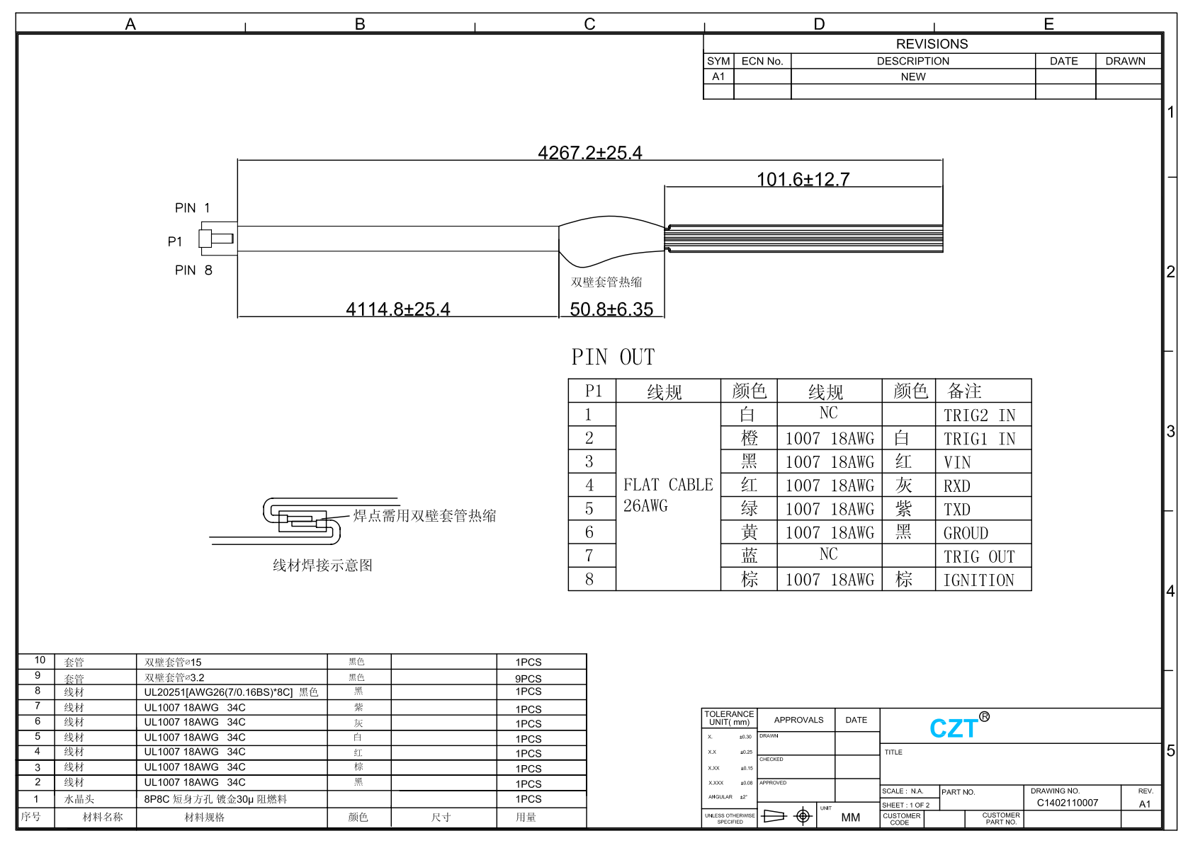
Figure 1. Official cable drawing. Endpoint and joining details show why splice identities and physical locations need controlled records for each actual assembly. CZT source · Original PDF, page 1.
Assign a stable identifier to each splice
Give every joining point a unique ID that appears in the schematic, connection table and harness drawing. List all participating wires and distinguish an intentional multiwire connection from separate wires that merely share a similar circuit name.
Record the splice's position using named harness datums. Define the measurement condition so its location can be inspected on a laid-out harness and understood after installation.
If several product variants use different circuits, identify which splice configurations belong to each orderable assembly. A master drawing should not make the operator choose a connection from memory.
Define the manufacturing detail
Specify the approved joining method and its supporting process reference. Include wire preparation, protective covering and any orientation or staggering requirements established by the design.
| Splice-map field | Required content |
|---|---|
| Splice ID | Unique reference across all documents |
| Participating wires | Explicit list of conductors and endpoints |
| Physical location | Dimension from a named datum |
| Process reference | Approved joining and inspection instructions |
| Protection | Defined insulation and mechanical treatment |
| Variant applicability | Assemblies using this exact configuration |
Do not assume that the joining process is acceptable because it produces electrical continuity. Qualification must address the actual conductor combination and relevant mechanical, electrical and environmental requirements.
Link the map to testing
Use the splice topology when defining the electrical test. Confirm that the test can identify the faults the product plan requires, rather than simply checking a convenient pair of endpoints.
For a hypothetical control harness, one supply wire may branch to several loads. A continuity reading at one load does not demonstrate that every branch is connected. The test map should represent the complete intended network and its relevant isolation relationships.
Where physical splice inspection occurs before covering, retain the agreed evidence and traceability. Later incoming inspection may not be able to view the joint without destroying the harness.

Figure 2. CZT document-management example. Splice identifiers, branch connections and variant applicability belong in the controlled manufacturing information. CZT source · Original image.
Define service and change boundaries
State whether the splice can be repaired and which authorized procedure applies. A manufacturing method should not automatically become a field-repair instruction.
When a wire or circuit is added, review joining capacity, protection, physical location and the test map. Release revised documents together so a correctly assembled old variant is not confused with an incorrect new one. A complete splice map makes manufacturing and service decisions reviewable without asking either team to reconstruct hidden joints from an electrical schematic alone.
Connect this review to CZT product information
Start with the relevant CZT product family and provide the original interface reference or controlled drawing. Ask which configurations and supporting documents are available for the task described here. Confirm the mating arrangement, required features and project conditions before choosing an orderable part.
Browse the relevant product family · View catalog resources
Discuss a drawing, sample or quotation
Share the part or family reference, current drawing revision, operating conditions and quantities. Include the specific checks described in this article so the inquiry identifies both the component and the evidence needed for your decision. Confirm sample availability and the proposed scope with the supplier.
Request a technical review or quotation
For broader context, read the related selection guide.