A panel-mount automotive connector should be reviewed as part of the complete panel, mating plug and cable installation. The nominal hole size is only one requirement. Panel thickness, sealing compression, fastening access and the space behind the connector all affect whether the assembly is usable.
Locate the relevant candidate through the automotive connector family, then obtain the exact mounting and mating drawings. Catalog identity is a starting point; it does not confirm panel suitability for a specific thickness or sealing condition.
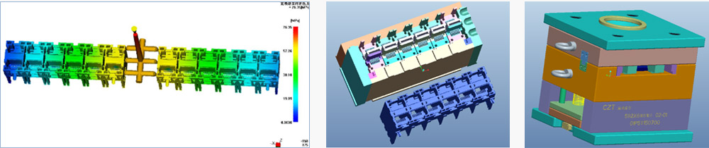
Figure 1. CZT tooling CAD examples. An installed-interface review needs controlled geometry, reference surfaces and the actual panel relationship. CZT source · Original image.
Define the panel references
Choose the surfaces that locate the connector and establish the hole pattern. Identify whether the connector is positioned by a flange, shoulder, fastener or another feature. Keep those references consistent between the connector and enclosure drawings.
Review tolerances for the opening, mounting holes, panel flatness and connector position. An acceptable fit at nominal size may leave insufficient clearance or uneven seal compression at another permitted combination.
Confirm the production process used to make the panel. A molded, machined or formed opening may need different controls to achieve the same functional geometry.
Inspect access on both sides
Place the entire mating plug and cable overmold in the assembly model. Check the insertion path, latch operation and required release-tool access. The installed port should be serviceable with the equipment in its intended maintenance condition.
Behind the panel, review cable bend space, wire exit angle and available support. Keep the cable from becoming the unintended lever that loads the connector whenever the equipment cover closes.
| Review area | Evidence to include |
|---|---|
| Panel engagement | Thickness range and locating section |
| Hole pattern | Dimensions, tolerances and datum scheme |
| Front access | Plug envelope and release clearance |
| Rear access | Cable routing and support layout |
| Sealing | Defined joint and compression conditions |
Where sealing is required, identify who controls the gasket and its installation. A seal inside the connector does not necessarily address the separate panel joint.
Trial the complete assembly
For a hypothetical mobile control unit, the connector may fit the panel but require a latch movement blocked by an adjacent bracket. Moving the hole or changing the bracket could solve the issue; selecting a different connector is another option. Test the chosen correction before freezing the panel tooling.
Use representative fasteners, mating parts and cable routing during the trial. Record tightening procedures and observed positional changes when they matter to alignment or sealing.

Figure 2. CZT coordinate-measurement equipment. Dimensions must be checked against the selected panel-interface drawing; this photograph does not establish a mounting tolerance. CZT source · Original image.
Release the installed configuration
Approve the connector model together with panel revision, mounting hardware and applicable cable envelope. Record fit, service access and sealing evaluations as separate results.
If an alternate changes flange depth or rear projection, revisit the complete arrangement even if its mating face appears unchanged. A controlled installed-assembly record gives mechanical engineering and purchasing a precise basis for deciding whether a proposed substitution fits the existing equipment without unreviewed modifications.
Connect this review to CZT product information
Start with the relevant CZT product family and provide the original interface reference or controlled drawing. Ask which configurations and supporting documents are available for the task described here. Confirm the mating arrangement, required features and project conditions before choosing an orderable part.
Browse the relevant product family · View catalog resources
Discuss a drawing, sample or quotation
Share the part or family reference, current drawing revision, operating conditions and quantities. Include the specific checks described in this article so the inquiry identifies both the component and the evidence needed for your decision. Confirm sample availability and the proposed scope with the supplier.
Request a technical review or quotation
For broader context, read the related selection guide.