Control a bent busbar's terminal positions from functional assembly datums, not from a collection of independent dimensions on a flat pattern. The important question is whether the finished contact faces and holes align with the equipment. A drawing should make those installed requirements measurable without forcing the inspector to guess how the part is located.
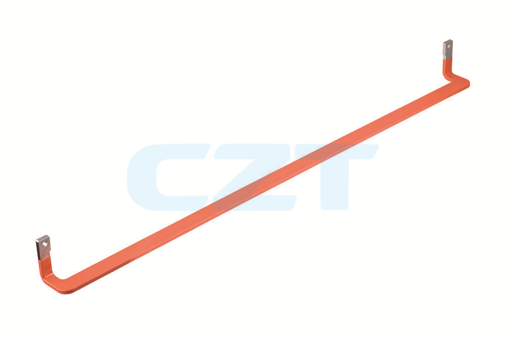
Figure 1. CZT formed rigid busbar illustrates separated terminal planes. Functional datums should control the installed positions after bending. CZT source · Original image.
Choose functional datums
Identify the surface or feature that establishes the busbar's position in the assembly. Then identify the features controlling rotation and remaining movement. Review those choices with both the mating-equipment designer and the manufacturer.
A flat blank may be useful for manufacturing, but its datum scheme is not necessarily the best one for checking the formed part. Keep the flat pattern and finished-part requirements consistent while stating which dimensions govern acceptance after forming.
Build the tolerance chain
Include material thickness, bend location, bend angle and the position of terminal holes relative to the final contact faces. Evaluate how their variations combine at the installed interface. A set of individually reasonable tolerances can still produce excessive terminal offset when stacked in the same direction.
Do not solve every fit issue by loosening hole tolerances. That can change contact overlap, hardware seating or electrical separation. Review which characteristic actually controls the functional failure and place the inspection effort there.
A formed-part drawing checklist
| Feature | Drawing or inspection definition |
|---|---|
| Primary contact face | Datum location and relevant flatness requirement |
| Terminal hole | Position relative to functional datums |
| Bent leg | Finished orientation and terminal-plane location |
| Contact overlap | Required mating area at assembly extremes |
| Inspection fixture | Locating method and permitted clamping |
Avoid forcing a flexible or thin part against a fixture until it appears correct unless that clamping condition represents the installation and is part of the agreed inspection method.

Figure 2. CZT formed coated busbars show bends and connection ends whose combined tolerances must be reviewed against the actual equipment interface. CZT source · Original image.
Use first articles to close the geometry
Measure the finished part using the proposed datum scheme and compare it with an assembly trial. Document whether fasteners enter freely and whether contact faces seat without unintended force. A part can accept the bolts while still loading a terminal because its contact planes are misaligned.
CZT's busbar power-distribution family provides a route for discussing formed custom parts. The catalog does not establish a specific bend tolerance or process capability. Request manufacturing feedback on the controlled drawing rather than placing a generic tolerance claim in the specification.
Use the same locating logic in the inspection fixture and the assembly review. If one holds the part by an unrelated edge, their results can disagree even when both measurements are repeatable.
If the supplier proposes a manufacturing change, ask which functional dimensions it affects and how the inspection record will demonstrate equivalence. Retain the approved first-article report and installed photographs with the drawing revision. This gives production a practical reference and makes later fit complaints traceable to the geometry that matters in the actual equipment.
Connect this review to CZT product information
Start with the relevant CZT product family and provide the original interface reference or controlled drawing. Ask which configurations and supporting documents are available for the task described here. Confirm the mating arrangement, required features and project conditions before choosing an orderable part.
Browse the relevant product family · View catalog resources
Discuss a drawing, sample or quotation
Share the part or family reference, current drawing revision, operating conditions and quantities. Include the specific checks described in this article so the inquiry identifies both the component and the evidence needed for your decision. Confirm sample availability and the proposed scope with the supplier.
Request a technical review or quotation
For broader context, read the related selection guide.