Busbar insulation edges should be designed around the actual conductive geometry, assembly tolerances and required electrical separation. Pay particular attention to holes, cut edges and the transition from an exposed contact zone to an insulated region. An insulation material's data sheet cannot establish the suitability of those finished details by itself.
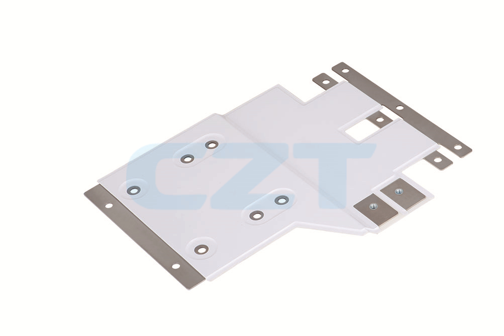
Figure 1. CZT laminated busbar shows exposed terminal regions beside insulated conductor areas, making edge and hole coverage explicit drawing-review subjects. CZT source · Original image.
Draw every exposed conductive region
Mark contact faces, hole walls, conductor edges and any hardware that becomes electrically connected after assembly. Include the mating component and fasteners. A metal washer or terminal can extend the conductive boundary beyond the nominal busbar outline.
Show insulation overhang, setbacks and coverage limits with controlled dimensions. Identify which edges are formed before insulation and which operations occur afterward. Later cutting, drilling or trimming may create a surface that differs from the one represented by an early material sample.
Establish the system requirement before dimensions
Collect operating voltage, transient requirements, environment, altitude and material information from the system design authority. Determine the applicable safety specification and current revision for the target equipment. Do not copy a clearance from an unrelated installation or treat coating thickness as interchangeable with an air gap.
CZT's energy-storage busbar family includes laminated and coated construction references. These names do not establish insulation thickness, edge-seal geometry or a qualified voltage. Request the actual layer stack and finished-edge definition.
Review critical details systematically
| Detail | Questions to close |
|---|---|
| Contact-zone boundary | Is the insulation setback controlled after assembly? |
| Fastener hole | Are hole walls and hardware included in the conductive boundary? |
| Outside corner | Can handling or forming damage the edge coverage? |
| Layer termination | Are voids, alignment and sealing details addressed? |
| Adjacent structure | Is separation maintained at tolerance extremes? |
Review an installed cross-section where a plan view hides the shortest path. A drawing can appear generous from above while a fastener head or turned edge creates a closer approach in section.
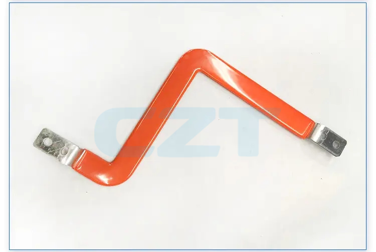
Figure 2. CZT insulated busbar example illustrates the transition from covered conductor to exposed end contacts; finished boundaries need construction-specific verification. CZT source · Original image.
Inspect and validate the finished construction
Choose dimensional and electrical checks that correspond to the design's critical features. Where a hidden edge cannot be inspected nondestructively, decide how process control, samples or sectioning will provide the required evidence. Document what each inspection can and cannot establish.
A hypothetical design change that enlarges a terminal washer can reduce separation even though the busbar and insulation drawings remain unchanged. Include mating hardware in change review so that this type of interaction is not missed.
Inspect the part after the intended assembly handling, not only immediately after insulation processing. A fixture or fastener can damage an otherwise acceptable edge; the verification boundary should include the operations that occur before the busbar is placed in service.
Release the insulation detail together with its installation boundary and verification record. Any later change to contact geometry, hardware, coating process or edge trimming should be assessed against that record. This keeps the electrical argument tied to the finished assembly rather than to the name of the insulating material.
Connect this review to CZT product information
Start with the relevant CZT product family and provide the original interface reference or controlled drawing. Ask which configurations and supporting documents are available for the task described here. Confirm the mating arrangement, required features and project conditions before choosing an orderable part.
Browse the relevant product family · View catalog resources
Discuss a drawing, sample or quotation
Share the part or family reference, current drawing revision, operating conditions and quantities. Include the specific checks described in this article so the inquiry identifies both the component and the evidence needed for your decision. Confirm sample availability and the proposed scope with the supplier.
Request a technical review or quotation
For broader context, read the related selection guide.