A busbar short-circuit-withstand specification must connect the fault duty to the complete installed conductor and support arrangement. Continuous-current performance cannot substitute for this evidence. Before booking a test, agree the fault waveform, protection behavior, fixture geometry and post-test acceptance requirements with the system designer and laboratory.
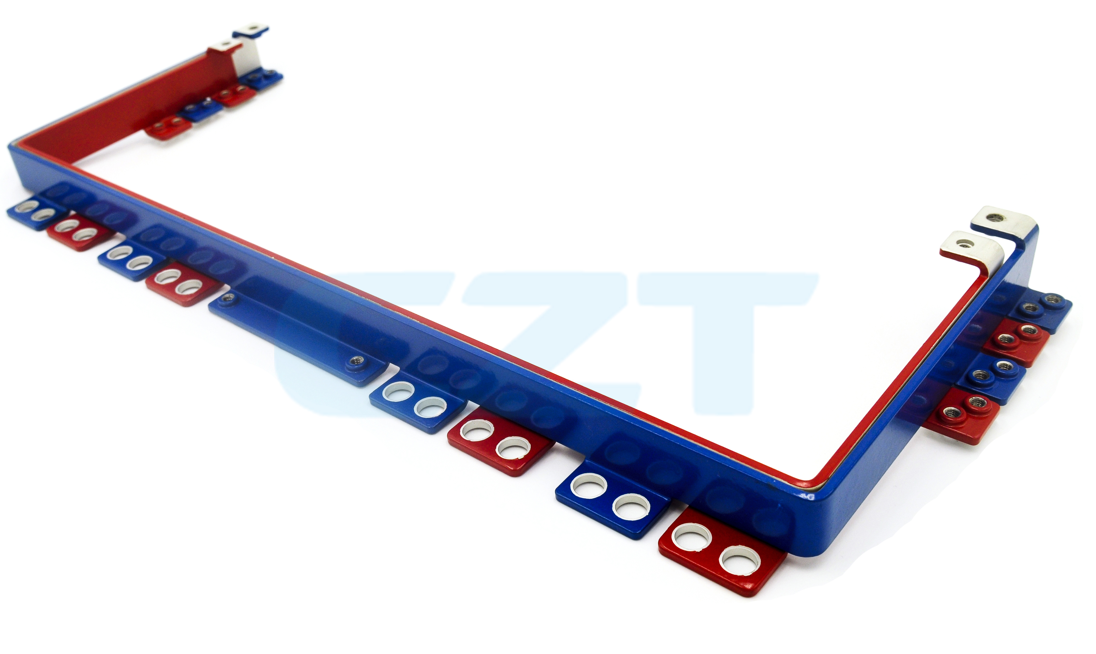
Figure 1. CZT distributed laminated busbar illustrates the importance of defining conductor geometry and connection locations in a short-circuit test specimen. CZT source · Original image.
Obtain the fault-duty inputs
Identify the source conditions and relevant protective device. Determine which current and duration characterize the intended duty, including the aspects required by the applicable product specification. Keep source prospective duty separate from the current actually limited by a protective device.
The responsible engineer should select the applicable standard and edition for the equipment. IEC's 61439-1 publication information describes assembly verification requirements and the relationship to relevant parts of that series. It does not mean that every ESS busbar is governed by the same equipment standard or test arrangement.
Define the physical test boundary
Show conductor shape, phase or polarity spacing, supports, joint hardware and terminal connections. Specify the actual support materials and fastening conditions. A strong laboratory fixture can make a conductor appear successful while omitting the support weakness present in the product.
Record whether the sample includes all significant joints and transitions. If the proposed specimen represents a larger family, document the technical basis for that representation. Do not assume that the longest or thickest member is automatically the only configuration that matters.
Prepare a laboratory handover checklist
| Input | Required agreement |
|---|---|
| Electrical duty | Waveform, magnitude, duration and protection boundary |
| Specimen | Drawing, material and assembly revision |
| Supports | Geometry, material and fastening method |
| Measurement | Current records and required observation channels |
| Acceptance | Defined damage, separation and electrical checks afterward |
| Reporting | Raw data, photographs and deviations from the plan |
The laboratory and design owner should resolve ambiguous inputs before the specimen is built. Reinterpreting the intended rating after a test is a poor substitute for an agreed specification.
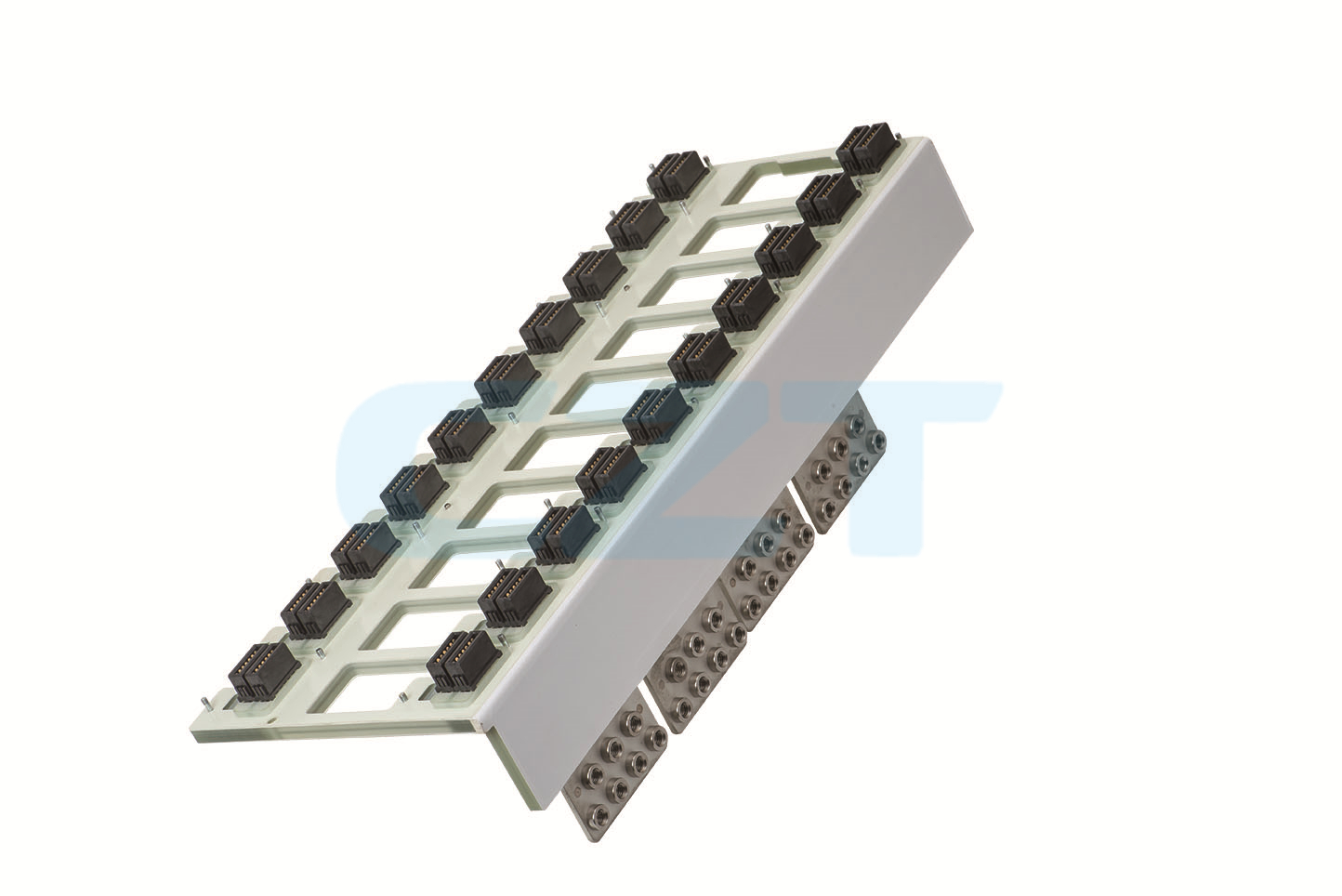
Figure 2. CZT integrated busbar assembly illustrates a larger installation boundary. Support and terminal conditions must accompany any fault-duty verification claim. CZT source · Original image.
Preserve the tested installation
Photograph the sample before and after the event, including support and joint locations. Record deformation and any required post-test insulation or functional checks. A brief visual statement that the bar remained intact may omit other acceptance requirements.
CZT's busbar power-distribution family provides product references for a construction review. The catalog does not demonstrate short-circuit performance for a custom support spacing or cabinet configuration.
Identify the required condition of the specimen after testing, including which functions must remain acceptable. Survival, continued serviceability and containment are different possible conclusions. The report should use the acceptance language agreed for the product rather than an informal statement that the test looked satisfactory.
The final evidence should state the tested duty and assembly boundary precisely. Changes to supports, conductor spacing, joints or protection can affect the applicability of that evidence. Keep those items in the change-control record so that a later installation is not described as verified solely because it uses the same conductor material.
Connect this review to CZT product information
Start with the relevant CZT product family and provide the original interface reference or controlled drawing. Ask which configurations and supporting documents are available for the task described here. Confirm the mating arrangement, required features and project conditions before choosing an orderable part.
Browse the relevant product family · View catalog resources
Discuss a drawing, sample or quotation
Share the part or family reference, current drawing revision, operating conditions and quantities. Include the specific checks described in this article so the inquiry identifies both the component and the evidence needed for your decision. Confirm sample availability and the proposed scope with the supplier.
Request a technical review or quotation
For broader context, read the related selection guide.