Every electronic device depends on connectors. Smartphones, electric vehicles, data centers, solar inverters, industrial robots — none of them work without reliable electrical connections. Yet few engineers or procurement professionals have a clear picture of how connectors are actually made.
The connector manufacturing process is a tightly sequenced chain of precision operations. A single automotive connector might contain stamped copper-alloy contacts plated in selective gold, housed in a glass-fiber-reinforced polymer shell, assembled on a high-speed automated line, and tested against electrical, dimensional, and environmental specifications — all before it ships in ESD-safe packaging to an assembly plant on the other side of the world.
Understanding each stage helps you ask better questions when choosing a connector manufacturer, evaluate supplier capabilities more accurately, and anticipate lead-time drivers. This article walks through the complete connector production cycle in eight stages, from initial design through final delivery.
Stage 1: Design and Engineering
Connector manufacturing begins long before any metal is cut. The design and engineering phase defines every dimension, material, tolerance, and performance target that downstream processes must hit.
CAD and 3D Modeling
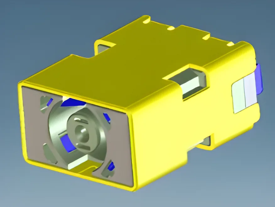
Engineers create detailed 3D models of the connector using CAD software such as CATIA, SolidWorks, or Creo. These models define the contact geometry, housing cavity layout, locking features, and mating interface. For a typical board-to-board connector with a 0.5 mm pitch, dimensional tolerances on the contact beam may be as tight as plus or minus 0.02 mm.
Simulation and CAE Analysis
Before committing to tooling, engineers run computer-aided engineering (CAE) simulations to validate the design virtually. Common simulations include:
- Finite Element Analysis (FEA) — Predicts stress distribution in contacts during mating and unmating cycles. Identifies potential fatigue failure points.
- Mold Flow Analysis — Simulates how molten plastic fills the injection mold cavity. Reveals potential short shots, weld lines, and sink marks before the mold is built.
- Thermal Simulation — Models heat generation and dissipation at rated current. Critical for high-power connectors used in EV charging and energy storage.
- Signal Integrity Simulation — For high-speed data connectors, electromagnetic modeling predicts crosstalk, insertion loss, and impedance matching.
Design for Manufacturability (DFM)
A connector that performs well on paper but cannot be manufactured consistently at scale is worthless. DFM reviews evaluate whether the design can be reliably stamped, molded, plated, and assembled using existing production equipment. Tooling engineers, quality engineers, and production managers participate in these reviews alongside the design team.
DFM considerations include minimum wall thickness for injection-molded housings, draft angles for mold release, strip layout efficiency for progressive die stamping, and plating accessibility for recessed contact surfaces.
Stage 2: Tooling and Mold Making
Tooling is the backbone of connector manufacturing. The precision of the stamping dies and injection molds directly determines the quality and consistency of every part produced. Tooling development typically represents the largest upfront investment and the longest lead-time item in a new connector program.
Precision Stamping Dies
Stamping dies are used to cut and form metal contacts from strip stock. A progressive die contains multiple stations, each performing a specific operation — blanking, piercing, bending, coining — as the metal strip advances through the die with each press stroke.
Die components are machined from tool steels such as SKD11 or DC53 using wire EDM (Electrical Discharge Machining) and precision grinding. Critical punch and die inserts are held to tolerances of plus or minus 0.005 mm. A well-built progressive die can produce millions of contacts before requiring regrinding or insert replacement.
Injection Molds
Connector housings are produced in injection molds, typically built from hardened steel (NAK80, S136, or H13). A single mold may contain 4 to 64 cavities, depending on part size and production volume requirements.
Mold construction involves CNC machining, EDM, and manual polishing. Cooling channel design is critical — uneven cooling causes warpage and dimensional variation in the molded housing. Modern molds use conformal cooling channels to maintain uniform temperature distribution across all cavities.
| Tooling Type | Typical Material | Tolerance | Expected Life |
|---|---|---|---|
| Progressive stamping die | SKD11 / DC53 tool steel | +/- 0.005 mm | 100-300 million strokes |
| Injection mold | NAK80 / S136 / H13 steel | +/- 0.01 mm | 1-5 million shots |
| Plating fixture | Titanium / engineered plastic | +/- 0.1 mm | 50,000-200,000 cycles |
Stage 3: Stamping and Forming
Stamping is where raw metal becomes a functional electrical contact. This stage converts flat strip stock into precisely shaped pins, sockets, spring beams, and terminals through a series of high-speed mechanical operations.
Material Selection
Contact materials are chosen based on conductivity, spring properties, and cost. The most common base metals include:
- Copper alloys (C2600, C5210, C7025) — Offer the best balance of electrical conductivity, mechanical strength, and formability. Phosphor bronze (C5210) is widely used for contacts requiring high spring retention force.
- Brass (C2680) — Lower cost than phosphor bronze, suitable for contacts with less demanding spring requirements.
- Beryllium copper (C1720) — Premium alloy with excellent fatigue resistance and conductivity. Used in high-reliability aerospace and military connectors.
Strip stock thickness typically ranges from 0.1 mm to 0.8 mm, depending on the connector type and current rating.
Progressive Die Stamping
In progressive die stamping, a coil of metal strip feeds into a high-speed press. With each stroke, the strip advances one pitch and every station in the die performs its operation simultaneously. A modern high-speed stamping press runs at 200 to 1,200 strokes per minute, producing finished contacts on a continuous carrier strip.
The carrier strip holds individual contacts in position throughout downstream processes — plating, insertion into housings, and final separation. This carrier-based approach enables automated handling and eliminates the need to orient loose parts.
Quality Monitoring During Stamping
In-die sensors monitor stamping force, strip feed accuracy, and part presence at each station. If a sensor detects an anomaly — a misfeed, a broken punch, a missing part — the press stops immediately. This prevents the production of defective parts and protects the die from damage.
Dimensional inspection of stamped contacts is performed using optical measurement systems and coordinate measuring machines (CMMs). Critical dimensions are checked against control plans derived from the product drawing.

Stage 4: Plating
Plating deposits a thin layer of metal onto the contact surface to improve electrical performance, corrosion resistance, and durability. It is one of the most technically demanding stages in the connector manufacturing process.
Why Plating Matters
The base copper alloy of a contact would oxidize rapidly if left unplated. Oxide layers increase contact resistance, generate heat, and eventually cause connection failure. Plating creates a stable, low-resistance interface that maintains reliable electrical contact over thousands of mating cycles and years of service.
Common Plating Materials
| Plating Type | Typical Thickness | Key Properties | Common Applications |
|---|---|---|---|
| Gold (Au) | 0.05 - 1.27 um | Lowest contact resistance, excellent corrosion resistance, high durability | Signal contacts, high-reliability applications |
| Tin (Sn) | 1.0 - 3.0 um | Good solderability, low cost, adequate corrosion resistance | Power contacts, PCB terminals |
| Nickel (Ni) | 1.0 - 3.0 um | Hard barrier layer, prevents copper migration | Underplate for gold and tin |
| Silver (Ag) | 1.0 - 5.0 um | Highest conductivity, good for high-current | High-power busbars, RF connectors |
| Palladium-Nickel (PdNi) | 0.5 - 1.5 um | Hard, wear-resistant, gold substitute | Automotive, telecom connectors |
Selective Plating
Plating precious metals like gold across the entire contact surface is wasteful and expensive. Selective plating applies gold only to the mating zone — the area that makes electrical contact — while using a lower-cost finish like tin on the solder tail. This approach can reduce gold consumption by 60 to 80 percent without compromising electrical performance.
Selective plating is achieved through masking techniques or spot plating on the continuous carrier strip. The carrier strip format from the stamping stage makes selective plating efficient because contacts are uniformly positioned and oriented.
Plating Process Control
Plating thickness, adhesion, porosity, and solderability are monitored continuously. X-ray fluorescence (XRF) analyzers measure plating thickness non-destructively. Salt spray testing (per ASTM B117) validates corrosion resistance. Solderability testing (per J-STD-002) confirms that plated surfaces accept solder reliably during PCB assembly.
Stage 5: Injection Molding
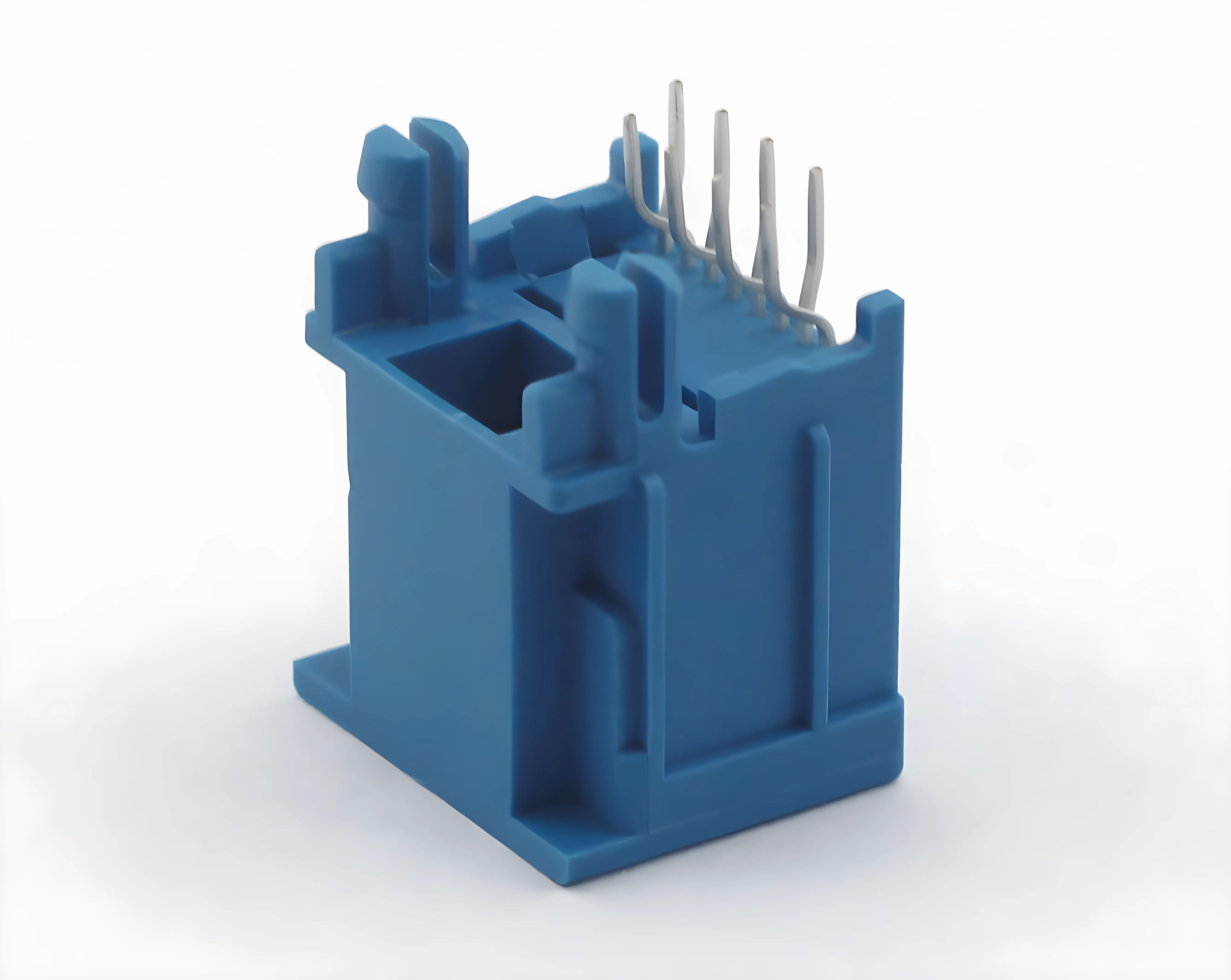
Injection molding produces the insulating housings that hold contacts in position, provide mechanical protection, and define the mating interface geometry. Material selection and process control at this stage directly affect the connector's electrical insulation, mechanical strength, and temperature resistance.
Housing Materials
Connector housings are molded from engineering thermoplastics selected for their dielectric strength, heat resistance, and mechanical properties.
| Material | Glass Fiber Content | Heat Resistance (UL 94) | Typical Use |
|---|---|---|---|
| LCP (Liquid Crystal Polymer) | 30-40% | V-0, up to 280 C | Fine-pitch SMT connectors, high-temp automotive |
| PBT (Polybutylene Terephthalate) | 30% | V-0, up to 220 C | General-purpose connectors, PCB headers |
| PA (Nylon / Polyamide) | 30-35% | V-0, up to 230 C | Industrial connectors, power terminals |
| PPS (Polyphenylene Sulfide) | 40% | V-0, up to 260 C | High-temp automotive, under-hood connectors |
LCP is the material of choice for fine-pitch connectors (0.4 mm to 0.8 mm pitch) because it flows easily into thin-wall sections and exhibits minimal warpage. PBT and PA are more cost-effective for larger connectors where thin-wall flow is less critical.
The Molding Cycle
A typical injection molding cycle for a connector housing takes 5 to 30 seconds, depending on part size and wall thickness. The cycle consists of four phases:
- Clamping — The mold halves close under high tonnage (50 to 500 tons depending on projected area).
- Injection — Molten plastic is injected into the mold cavity at pressures of 800 to 2,000 bar. Fill time for a small connector housing is typically under one second.
- Cooling — The part solidifies in the mold. Cooling time accounts for 50 to 70 percent of the total cycle.
- Ejection — The mold opens and ejector pins push the finished part out.
Process Monitoring
Modern molding machines monitor cavity pressure, melt temperature, injection speed, and cushion position in real time. Statistical process control (SPC) charts track critical dimensions across production runs. Cavity pressure sensors detect short shots and flash conditions within the cycle, enabling automatic rejection of suspect parts.
Stage 6: Assembly
Assembly brings together the stamped and plated contacts, molded housings, and any additional components (seals, latches, shields) into a finished connector. The assembly method depends on production volume, connector complexity, and required precision.
Automated Assembly
High-volume connectors are assembled on fully automated lines. Contacts are fed from the carrier strip and inserted into housing cavities by precision insertion heads. Insertion force and depth are monitored for every contact. A typical automated assembly line runs at 6,000 to 20,000 parts per hour.
Automated vision systems inspect each assembled connector for missing contacts, bent pins, incorrect seating depth, and housing defects. Parts that fail inspection are automatically diverted to a reject bin.
Semi-Automated Assembly
For lower-volume or more complex connectors — such as those with multiple seal layers, secondary locks, or hybrid signal-and-power configurations — semi-automated assembly combines machine insertion with manual operations. Operators load components and perform operations that require dexterity or judgment, while machines handle repetitive insertion and inspection tasks.
Insert Molding
Some connectors use insert molding, where stamped contacts are placed into the mold before plastic is injected around them. This creates a single integrated part with contacts permanently locked into the housing. Insert molding eliminates the separate assembly step and produces a more robust mechanical bond between contact and housing. It is common in sealed automotive connectors and high-vibration industrial applications.
Stage 7: Testing and Quality Control
Testing is not the final checkpoint — it is woven throughout the connector manufacturing process. However, finished-product testing provides the definitive confirmation that every assembled connector meets its specification before it ships to the customer.
Electrical Testing
- Contact resistance — Measured at the milliohm level using a four-wire (Kelvin) method. Verifies that plating quality and contact normal force produce a stable, low-resistance connection.
- Insulation resistance — Confirms that the housing material provides adequate isolation between adjacent contacts. Typical requirement: greater than 100 megaohms at 500 VDC.
- Dielectric withstand voltage (Hi-Pot) — Applies a high voltage between contacts and between contacts and ground to verify insulation integrity. Tests are typically conducted at 500 to 1,500 VAC for one minute.
- Continuity — Confirms that every contact in a multi-pin connector is electrically connected through the mating interface.
Dimensional Inspection
Coordinate measuring machines (CMMs) and optical comparators verify critical dimensions: true position of contacts, housing cavity spacing, overall connector height, and mating interface geometry. For high-volume production, automated optical inspection (AOI) systems measure dimensions at line speed.
Environmental and Reliability Testing
Environmental tests validate that the connector will perform reliably under real-world conditions. These tests are typically performed on sample quantities per lot, following standards such as EIA-364 or IEC 60512.
| Test | Standard | What It Validates |
|---|---|---|
| Temperature cycling | EIA-364-32 | Resistance to thermal expansion and contraction |
| Salt spray | ASTM B117 | Corrosion resistance of plated surfaces |
| Vibration | EIA-364-28 | Contact retention under mechanical vibration |
| Humidity | EIA-364-31 | Insulation performance in high-moisture environments |
| Mating durability | EIA-364-09 | Contact resistance stability over repeated mating cycles |
| Current cycling | EIA-364-70 | Temperature rise under rated current load |
For a deeper look at the certifications and standards that govern connector testing, see our guide to connector certifications.
Stage 8: Packaging and Shipping
The final stage protects finished connectors during storage and transit. Packaging may seem straightforward, but improper packaging can undo all the precision work of the previous seven stages.
ESD Protection
Many connectors — especially those with fine-pitch contacts or gold plating — are sensitive to electrostatic discharge. ESD-safe packaging uses conductive or dissipative materials (anti-static bags, conductive trays, carbon-loaded foam) to prevent static buildup and discharge events that could damage plating or degrade contact surfaces.
Moisture Barrier Packaging
Connectors destined for surface-mount (SMT) assembly must be packaged in moisture-barrier bags with desiccant, per IPC/JEDEC J-STD-033. If the housing absorbs moisture during storage and is then exposed to reflow soldering temperatures (peak 260 degrees Celsius), the trapped moisture can vaporize and cause "popcorning" — internal delamination or cracking of the housing.
Packaging Formats
| Format | Description | Typical Use |
|---|---|---|
| Tape and reel | Contacts or connectors sealed in carrier tape on a reel | SMT pick-and-place assembly |
| Tube (stick) magazine | Parts loaded into anti-static tubes | Through-hole auto-insertion |
| Tray | Parts arranged in molded trays | Larger connectors, manual assembly |
| Bulk bag | Parts loose in ESD-safe bags | Low-volume or non-automated assembly |
Labeling includes part number, lot number, quantity, date code, and RoHS compliance marking. Traceability data links every shipping container back to specific production lots, raw material batches, and test records.
CZT's Connector Manufacturing Capabilities
CZT (Shenzhen Deren Electronic Co., Ltd., SZSE: 002897) has been manufacturing precision connectors for over 30 years. What started as a small stamping operation has grown into a vertically integrated connector manufacturer serving automotive, telecommunications, consumer electronics, new energy, and industrial markets worldwide.
Production Scale
CZT operates multiple manufacturing facilities equipped with over 500 high-speed stamping presses, hundreds of injection molding machines, and fully automated assembly and plating lines. This scale enables CZT to handle production volumes ranging from prototype quantities to hundreds of millions of connectors per year.
Vertical Integration
CZT controls every stage of the connector manufacturing process in-house — from tool and die design through stamping, plating, molding, assembly, and testing. Vertical integration eliminates the quality risks and lead-time delays that come with outsourcing critical processes. When an issue arises, CZT's engineering team can trace it to the root cause and implement corrective action without waiting on external suppliers.
Quality Systems and Certifications
CZT holds IATF 16949 (automotive quality management), ISO 9001, ISO 14001 (environmental management), and multiple product-level certifications including UL and CE. These certifications are not just maintained — they are actively used to drive continuous improvement across every production line.
Engineering Support
CZT's engineering team works directly with customers on custom connector design, DFM optimization, and application-specific material selection. Whether you need a modified standard product or a fully custom connector, CZT provides the design simulation, prototyping, and validation support to move from concept to mass production efficiently.
Learn more about CZT's history, capabilities, and global reach on our About page, or browse our full product catalog.
Frequently Asked Questions
How long does it take to manufacture a new connector from scratch?
The total timeline from initial design to mass production typically ranges from 12 to 20 weeks. Tooling development (stamping dies and injection molds) accounts for the largest portion — usually 8 to 14 weeks. Design and engineering take 2 to 4 weeks, and first-article validation adds another 2 to 4 weeks. Once tooling is validated, ongoing production lead times are much shorter, typically 4 to 8 weeks depending on volume and plating requirements.
What is the most critical stage in the connector manufacturing process?
Tooling. The precision of the stamping dies and injection molds sets the quality ceiling for everything that follows. A die built to plus or minus 0.005 mm tolerances will produce consistent contacts for hundreds of millions of strokes. A poorly built die will produce dimensional variation that no amount of downstream inspection can fix. Investing in high-quality tooling upfront reduces scrap, rework, and field failures over the life of the product.
Why is gold plating used on connector contacts instead of a cheaper metal?
Gold does not oxidize under normal conditions, which means gold-plated contacts maintain low and stable contact resistance over time. This is critical for signal-level connections where even small increases in resistance can degrade signal integrity. Gold also provides excellent wear resistance through thousands of mating cycles. For power contacts where signal integrity is less critical, tin plating offers a cost-effective alternative with good solderability and adequate corrosion resistance.
What quality certifications should a connector manufacturer hold?
At minimum, look for ISO 9001 (quality management) and product-level certifications such as UL (safety) and RoHS (environmental compliance). For automotive applications, IATF 16949 is essential. For products sold in Europe, CE marking is required. Additional certifications like ISO 14001 (environmental management) and ISO 45001 (occupational health and safety) indicate a manufacturer with mature, well-managed operations. See our complete connector certifications guide for details on each standard.
Can CZT produce custom connectors for specific applications?
Yes. CZT's in-house tooling, engineering, and production capabilities support fully custom connector development. The process starts with a design review where CZT's engineers work with your team to define requirements, optimize the design for manufacturability, and select appropriate materials and plating. CZT then builds dedicated tooling, produces first-article samples for validation, and scales to mass production. Contact our engineering team to discuss your custom connector requirements.
Partner with CZT for Your Next Connector Program
Whether you need a standard catalog connector or a fully custom solution, CZT brings 30-plus years of manufacturing expertise, vertically integrated production, and rigorous quality systems to every project. Our engineering team is ready to support you from initial design through volume production and global delivery.
Explore our product catalog to see our full range of connector solutions, or contact us directly to discuss your specific requirements with a CZT engineer.