A modern passenger vehicle contains over 1,500 individual wires totaling more than 1.5 miles in length. In industrial equipment, the numbers can be even higher. The wiring harness that organizes, protects, and routes all of those conductors is one of the most labor-intensive and mission-critical subsystems in any electromechanical product.
Poor wire harness design leads to warranty claims, field failures, and costly recalls. Good design leads to reliable systems that last the full service life of the vehicle or machine. The difference comes down to engineering discipline applied early in the development cycle.
This guide covers the complete wire harness design process from schematic to production, with practical recommendations for material selection, routing, testing, and quality control. Whether you are designing your first prototype harness or optimizing an existing production design, these best practices will help you avoid the most common and expensive mistakes.

What Is a Wire Harness?
A wire harness (also called a wiring harness or wire harness assembly) is a bundled arrangement of wires, cables, connectors, and terminals that transmits electrical power and signals throughout a vehicle, machine, or device. The harness holds individual circuits together in an organized structure that can be manufactured as a single unit and installed in one step during final assembly.
A typical wiring harness includes the following components:
- Wires and cables. The conductors that carry current. Wire gauge is selected based on the current load and allowable voltage drop for each circuit.
- Connectors. The interface points where the harness plugs into ECUs, sensors, actuators, and other devices. Connector selection is critical for reliability. See our guide to wire connector types for a detailed overview.
- Terminals and contacts. The metal components crimped or soldered onto wire ends that make the electrical connection inside each connector housing.
- Protective sleeving. Corrugated tubing, braided loom, or heat-shrink tubing that shields wire bundles from abrasion, heat, and chemicals.
- Tape and binding. Harness tape, cable ties, and clips that hold the bundle together and secure it to the vehicle or equipment frame.
- Seals and grommets. Rubber or silicone components that prevent moisture and contaminants from entering connectors and pass-through points.
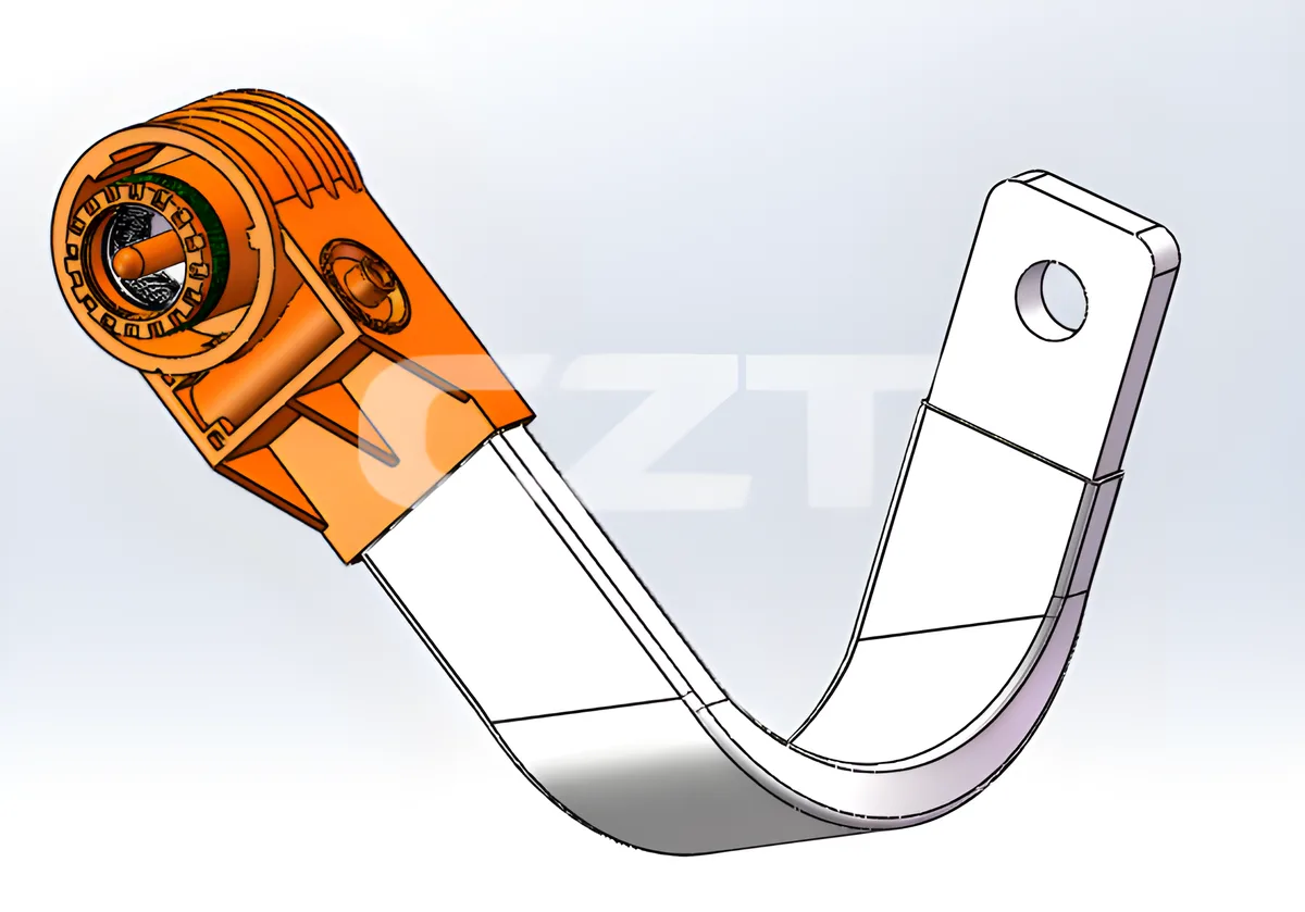
The harness serves as the central nervous system of any electrical system. A well-designed harness simplifies manufacturing, reduces assembly time, and dramatically improves long-term reliability.
Wire Harness vs Cable Assembly: Key Differences
The terms "wire harness" and "cable assembly" are often used interchangeably, but they refer to different products with different design requirements. Understanding the distinction matters when specifying components or communicating with your manufacturing partner.
| Feature | Wire Harness | Cable Assembly |
|---|---|---|
| Structure | Multiple individual wires bound together with tape, ties, or loom | Multiple conductors enclosed in a single outer jacket |
| Flexibility | More flexible; individual wires can branch in different directions | Less flexible; fixed bundle within jacket |
| Environmental protection | Relies on external sleeving, tape, and connector seals | Outer jacket provides inherent protection |
| Typical application | Interior vehicle wiring, control panels, appliance internals | Outdoor connections, inter-equipment links, data transmission |
| Branching | Supports complex branching and breakouts | Typically point-to-point with no branching |
| Cost | Lower material cost; higher labor cost | Higher material cost; lower labor cost |
| Customization | Highly customizable routing and circuit configuration | Standardized configurations more common |
In practice, most automotive and industrial electrical systems use a combination of both. The main body harness inside a vehicle is a wire harness with dozens of branches, while the connection between a trailer and a tow vehicle is typically a cable assembly.
Wire Harness Design Process Overview
Effective wire harness design follows a structured process that moves from electrical requirements through physical design, prototyping, validation, and production release. Skipping steps or compressing the timeline almost always results in quality problems downstream.
Step 1: Schematic and Circuit Design
Every harness starts with an electrical schematic that defines every circuit, including wire gauge, color code, connector pin assignment, and fuse or relay protection. The schematic is the single source of truth for the entire design.
Key deliverables at this stage include the circuit list, connector pinout tables, and a fuse and relay assignment chart. Modern teams use ECAD tools such as Capital Harness, Zuken E3, or CATIA Electrical to manage this data.
Step 2: 3D Routing and Packaging
The schematic defines what needs to be connected. Routing defines how. Using a 3D CAD model of the vehicle or equipment, engineers route wire bundles along available pathways, avoiding heat sources, moving parts, and sharp edges.
Routing decisions directly affect harness length, weight, and cost. A 10% reduction in total wire length across a production run of 100,000 vehicles saves significant material and weight. This step also defines clip locations, grommet positions, and connector mounting points.
Step 3: Prototyping
Before committing to production tooling, build prototype harnesses on a full-scale formboard (also called a nail board or assembly board). The prototype validates wire lengths, connector positions, and branch breakout locations against the actual vehicle or equipment.
Prototype builds also reveal manufacturing challenges. If a particular branch is difficult to tape or a connector is hard to reach during installation, it is far cheaper to fix the design at this stage than after production tooling is complete.
Step 4: Testing and Validation
Prototype harnesses undergo electrical testing (continuity, isolation, hipot) and physical validation (fit checks, vibration, thermal cycling). We cover testing standards in detail in a later section.
Validation should include installation trials on actual production hardware. A harness that tests perfectly on the bench can still fail if it does not fit the installation envelope or if service technicians cannot access the connectors for maintenance.
Step 5: Production Release
Once the design is validated, the engineering team releases a complete manufacturing package that includes the formboard drawing, bill of materials, assembly instructions, test specifications, and quality control plan. This package must be detailed enough that a contract manufacturer can build the harness without ambiguity.
Key Design Considerations
The following technical factors should be evaluated for every circuit in the harness. Getting any one of them wrong can cause intermittent failures, overheating, or premature degradation.
Current Capacity and Wire Sizing
Every wire must be sized to carry its maximum expected current with an adequate safety margin. Undersized wire overheats, degrades insulation, and can cause fires. The standard reference for automotive wire sizing is SAE J1128, which defines current ratings for various wire gauges and insulation types at specific ambient temperatures.
| AWG | Cross Section (mm2) | Max Current at 85C Ambient (GPT) | Typical Application |
|---|---|---|---|
| 20 | 0.5 | 5 A | Sensor signals, LED indicators |
| 18 | 0.75 | 7 A | Instrument cluster, switches |
| 16 | 1.0 | 10 A | Interior lighting, small motors |
| 14 | 2.0 | 15 A | Power windows, seat motors |
| 12 | 3.0 | 20 A | Headlamps, fuel pump |
| 10 | 5.0 | 30 A | Blower motor, heated seats |
| 8 | 8.0 | 46 A | Starter circuit, high-current loads |
Always derate wire capacity when routing through high-temperature zones such as engine compartments. A wire rated for 10 A at 85C ambient may only handle 7 A at 125C.
Voltage Drop
Voltage drop across a circuit must stay within the tolerance of the load device. Most automotive ECUs and sensors require supply voltage within plus or minus 10% of nominal. For a 12 V system, that means no more than 1.2 V total drop across the entire circuit, including connectors and splices.
Calculate voltage drop using the formula: V_drop = I x R x L x 2, where I is current in amps, R is resistance per unit length, L is one-way wire length, and the factor of 2 accounts for the return path. Use this calculation to verify that your wire gauge selection meets voltage drop requirements, not just current capacity.
EMI Shielding
Sensitive signal circuits (CAN bus, LIN bus, sensor signals) require shielding from electromagnetic interference. Shielded twisted-pair wire is the standard solution for automotive data buses. The shield must be properly grounded at one end (typically the ECU end) to be effective.
Route signal wires away from high-current power circuits whenever possible. Maintain a minimum separation distance of 50 mm between unshielded signal wires and power wires carrying more than 10 A.
Bend Radius
Every wire and cable has a minimum bend radius below which the conductor or insulation can be damaged. The general rule for standard automotive wire is a minimum bend radius of 3 to 5 times the outer diameter of the wire or bundle. For coaxial cables and shielded cables, the minimum is typically 6 to 10 times the outer diameter.
Violating minimum bend radius causes insulation cracking, conductor fatigue, and impedance changes in signal cables. Pay special attention to bend radius at connector entry points and where harness branches break out from the main trunk.
Temperature Rating
Every component in the harness must be rated for the maximum temperature it will experience in service. Engine compartment temperatures can exceed 150C near exhaust manifolds. Interior temperatures rarely exceed 85C but can reach 105C near the dashboard in direct sunlight.
Map the thermal zones of your vehicle or equipment and specify insulation materials accordingly. Using a single high-temperature wire type everywhere is safe but expensive. Using zone-appropriate materials optimizes cost without compromising reliability.
Material Selection
Wire Types
Automotive primary wire is classified by insulation material and wall thickness. The most common types defined by SAE J1128 are:
| Wire Type | Insulation | Wall Thickness | Temperature Rating | Key Properties |
|---|---|---|---|---|
| GPT | PVC | Standard | 80C | Low cost, general purpose |
| GXL | Cross-linked PE | Thin wall | 125C | Reduced diameter and weight, good chemical resistance |
| TXL | Cross-linked PE | Extra thin wall | 125C | Minimum diameter and weight, tight routing |
| SXL | Cross-linked PE | Standard wall | 125C | Maximum abrasion resistance, engine compartment |
| XLPE | Cross-linked PE | Varies | 150C | High-temperature zones near exhaust |
For most new automotive designs, GXL and TXL wire have largely replaced GPT as the default choice. The cross-linked polyethylene insulation offers better temperature resistance, chemical resistance, and abrasion resistance in a thinner wall, which reduces harness diameter and weight.
Insulation Materials
Beyond the wire itself, protective sleeving and wrapping materials must be matched to the environment:
- Corrugated polyamide (nylon) tubing. Standard protection for underbody and engine compartment routing. Temperature range of -40C to 150C. Excellent abrasion resistance.
- PVC split loom. Lower cost option for interior and trunk routing where temperatures stay below 105C.
- Braided fiberglass sleeving. Used near exhaust systems and other extreme heat sources. Rated to 250C or higher.
- Heat-shrink tubing. Used at branch breakouts, splice points, and connector transitions. Provides a sealed, strain-relieved transition.
- Harness tape. Cloth-backed adhesive tape (such as Tesa or Coroplast automotive tape) used to bind wire bundles. Fleece-backed tape provides noise damping in interior applications.
Connector Selection
Choosing the right connector for each interface point is one of the most consequential decisions in harness design. Key selection criteria include:
- Pin count and circuit configuration. Match the connector to the number of circuits required, with room for spare pins if future expansion is anticipated.
- Current rating per contact. Ensure each contact can handle the maximum circuit current with margin.
- Environmental sealing. Use sealed connectors (IP67 or higher) for any location exposed to moisture, dust, or washdown. See our automotive connector IP ratings guide for details.
- Mating cycles. Service connectors that will be disconnected and reconnected during maintenance need higher mating cycle ratings than permanent connections.
- Keying and polarization. Prevent mis-mating by specifying unique keying for connectors with similar pin counts in the same area of the harness.
CZT manufactures a full range of automotive connectors and terminals designed for wire harness applications, including sealed multi-pin connectors, high-current single-pin connectors, and Deutsch-compatible alternatives.
Wire Harness Testing Standards
Every production wiring harness must be tested before it ships. The industry-standard quality benchmark is IPC/WHMA-A-620, titled "Requirements and Acceptance for Cable and Wire Harness Assemblies." This standard defines three classes of acceptance criteria:
- Class 1. General electronic products. Basic functionality requirements.
- Class 2. Dedicated service electronic products. Extended life and reliable performance expected.
- Class 3. High-reliability electronic products. Continued performance under harsh conditions is critical (aerospace, military, medical, automotive safety systems).
Most automotive and industrial harnesses are built to Class 2 or Class 3 requirements.
Electrical Tests
| Test | Purpose | Method | Accept Criteria |
|---|---|---|---|
| Continuity | Verify every circuit is connected correctly | Low-voltage resistance measurement, pin-to-pin | Resistance below specified maximum (typically less than 50 milliohms per connection) |
| Isolation (Hipot) | Verify no unintended connections between circuits | Apply high voltage (500-1500 VDC) between adjacent circuits | No breakdown or leakage above threshold |
| Voltage drop | Verify circuit resistance under load | Apply rated current and measure end-to-end voltage drop | Drop within specification for each circuit |
Mechanical Tests
| Test | Purpose | Method | Accept Criteria |
|---|---|---|---|
| Pull force (crimp) | Verify terminal crimp integrity | Pull terminal from wire at specified rate | Meets minimum pull force per wire gauge (per UL 486A or IPC/WHMA-A-620) |
| Connector insertion force | Verify proper terminal seating | Measure force to insert and extract terminal from housing | Within connector manufacturer specification |
| Bend test | Verify harness flexibility at breakout points | Flex harness branch through specified angle and cycles | No insulation cracking or conductor breakage |
Environmental Tests
| Test | Purpose | Conditions |
|---|---|---|
| Thermal cycling | Validate performance across temperature range | -40C to +125C, 100+ cycles |
| Salt spray | Validate corrosion resistance of connectors and terminals | 96-hour salt fog per ASTM B117 |
| Vibration | Validate resistance to mechanical fatigue | Random vibration per vehicle OEM specification |
| Fluid resistance | Validate insulation against automotive fluids | Immersion in fuel, oil, brake fluid, coolant |
100% electrical testing (continuity and isolation) on every production harness is non-negotiable. Mechanical and environmental tests are typically performed on sample basis during design validation and periodic production audits.
Common Wire Harness Design Mistakes to Avoid
Years of manufacturing and field experience have revealed a consistent set of design errors that cause the majority of harness-related failures. Avoiding these mistakes will save time, money, and warranty cost.
1. Insufficient strain relief. Wires that flex repeatedly at a connector entry point without proper strain relief will fatigue and break. Always specify strain relief boots, cable ties with edge clips, or molded connector backshells at any point where the harness moves relative to the connector.
2. Ignoring thermal derating. Wire current ratings published in datasheets assume a specific ambient temperature. Routing a wire rated for 10 A at 85C through a 125C engine compartment without derating is a fire risk. Always apply temperature derating factors.
3. Over-bundling. Packing too many current-carrying wires into a tight bundle creates mutual heating that reduces the effective current capacity of every wire in the bundle. Apply bundle derating factors when more than three current-carrying conductors are grouped together.
4. Poor connector specification. Choosing a connector based solely on pin count without considering sealing, temperature rating, current rating, and mating cycles leads to field failures. Specify connectors as carefully as you specify wire.
5. Missing service access. Designing a harness that cannot be serviced without removing major vehicle components frustrates technicians and increases warranty repair costs. Ensure that every connector that may need to be disconnected during the vehicle's service life is accessible with standard tools.
6. Inadequate documentation. A harness that cannot be built consistently from the documentation package will have quality variation from unit to unit. Invest in clear, complete formboard drawings and assembly instructions.
7. Skipping prototype validation. Going directly from CAD to production tooling without building and testing physical prototypes is a gamble that rarely pays off. Prototype builds catch routing conflicts, length errors, and installation problems that are invisible in the digital model.
Automotive vs Industrial Wire Harness Requirements
While the fundamental principles of wire harness design apply across industries, automotive and industrial applications have different priorities and constraints. Understanding these differences is essential when transitioning a design between sectors or selecting a manufacturing partner.
| Requirement | Automotive | Industrial |
|---|---|---|
| Production volume | High (thousands to millions per year) | Low to medium (tens to thousands per year) |
| Design lifecycle | 5-7 year vehicle program | 10-20+ year equipment lifecycle |
| Temperature range | -40C to +150C (engine compartment) | -20C to +80C (typical); up to +200C (furnace/kiln) |
| Vibration | Continuous, random, multi-axis | Intermittent, often single-axis |
| Chemical exposure | Fuel, oil, coolant, road salt | Hydraulic fluid, solvents, cutting oils (varies by industry) |
| Regulatory standards | OEM-specific + SAE + ISO | IEC, UL, NEC, application-specific |
| Weight sensitivity | High (affects fuel economy and range) | Low to moderate |
| Cost pressure | Extreme (cents per harness matter) | Moderate (reliability valued over cost) |
| Connector preference | Application-specific sealed connectors | Deutsch, M12, circular MIL-spec, terminal blocks |
| Assembly method | Formboard with guided assembly | Bench build, often by skilled technicians |
For automotive applications, CZT provides high-volume connector and terminal solutions optimized for automated crimping and assembly. For industrial applications, our engineering team works with customers to develop custom harness connector solutions that meet specific environmental and performance requirements. Learn more about our automotive and EV solutions.
Frequently Asked Questions
What is the difference between a wire harness and a wiring loom?
The terms are functionally interchangeable. "Wire harness" and "wiring harness" are the standard terms in North America, while "wiring loom" is more commonly used in the United Kingdom, Australia, and other Commonwealth countries. Both refer to the same product: a bundled assembly of wires, connectors, and protective materials designed to be installed as a single unit.
How long does it take to design a wire harness?
A simple harness with fewer than 20 circuits can be designed in one to two weeks. A full vehicle body harness with 200+ circuits typically requires three to six months from initial schematic through production release, including prototype builds and validation testing. The timeline depends heavily on the complexity of the electrical system and the maturity of the vehicle or equipment platform.
What software is used for wire harness design?
The most widely used wire harness design tools include Capital Harness (Siemens), Zuken E3.series, CATIA Electrical (Dassault Systemes), EPLAN Harness proD, and Solidworks Electrical. These tools manage the complete workflow from schematic capture through 3D routing, formboard generation, and manufacturing documentation. Smaller projects sometimes use general-purpose CAD tools with manual documentation.
Can a wire harness be repaired in the field?
Yes, but with limitations. Individual wires can be spliced using butt connectors or solder-and-heat-shrink methods. Damaged connectors can be replaced if the terminals can be extracted and re-inserted. However, extensive harness damage (such as from a rodent chew-through or fire) usually requires full harness replacement. Field repairs should follow the equipment manufacturer's approved repair procedures to maintain warranty coverage and safety compliance.
What certifications should a wire harness manufacturer have?
At minimum, look for IATF 16949 (automotive quality management), ISO 9001 (general quality management), and IPC/WHMA-A-620 certified operators. For specific industries, additional certifications may be required: UL/CSA for North American electrical products, ISO 13485 for medical devices, or AS9100 for aerospace. CZT holds IATF 16949 and ISO 9001 certifications and manufactures connectors and terminals to IPC/WHMA-A-620 Class 2 and Class 3 standards.
Start Your Wire Harness Project with CZT
Designing a reliable wiring harness starts with choosing the right components. CZT (SZSE: 002897) is a leading Chinese connector manufacturer supplying automotive and industrial connectors, terminals, and seals to OEMs and Tier 1 suppliers worldwide.
Whether you need standard automotive connectors for a high-volume production harness or custom connector solutions for a specialized industrial application, our engineering team is ready to support your project from design through mass production.
- Browse our automotive connector catalog: Automotive Connectors
- Discuss your project requirements: Contact CZT Engineering


