Every electrical system depends on wire connectors. From a simple household appliance to a high-voltage EV battery pack, the connector is the point where reliability is either built in or designed out. A poor connector choice leads to voltage drops, intermittent failures, overheating, and — in safety-critical applications — fire.
The challenge is that types of wire connectors number in the thousands. Crimp terminals, terminal blocks, wire-to-board interfaces, sealed automotive housings, and insulation displacement connectors each serve different purposes. Choosing the right one requires matching electrical ratings, wire gauge, environmental exposure, and mechanical demands to the application.
This guide covers every major category of electrical wire connectors used in automotive, industrial, telecom, and consumer electronics. We include specifications, comparison tables, and selection criteria so you can make confident engineering decisions. If you need connectors for automotive or EV applications, we cover those in dedicated detail.
What Is a Wire Connector?
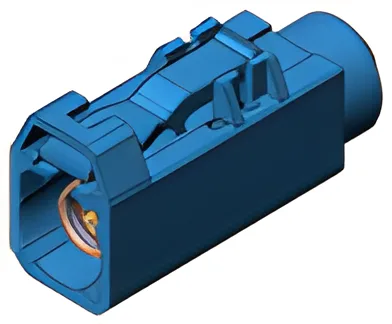
A wire connector is a device that joins an electrical conductor to another conductor, a terminal, or a piece of equipment. Its job is simple: maintain a low-resistance, mechanically secure electrical path under the conditions the circuit will face.
That definition sounds basic, but the engineering behind it is not. A wire connector must handle rated current without excessive heat rise, resist vibration and mechanical stress, tolerate the operating temperature range, and — in many cases — seal against moisture, dust, or chemical exposure.
Proper connector selection matters because the connector is almost always the weakest link in a wiring system. Copper wire itself rarely fails. Connectors fail when they are undersized, improperly crimped, exposed to conditions they were not designed for, or simply the wrong type for the application. The cost of a connector is trivial compared to the cost of a field failure.
Wire connector types are classified by their termination method (crimp, solder, IDC, screw), their mating interface (wire-to-wire, wire-to-board, wire-to-panel), and their environmental rating (open, sealed, hermetic). The sections below walk through each major category.
Crimp Connectors
Crimp connectors are the most widely used types of wire connectors in both industrial and automotive wiring. A crimp connection works by mechanically deforming a metal barrel around a stripped wire, creating a gas-tight joint that resists corrosion and maintains low contact resistance.
Crimping is preferred over soldering in most production environments because it is faster, more repeatable, and does not introduce heat that can damage wire insulation. When done with calibrated tooling, a crimp joint is actually stronger and more reliable than a solder joint under vibration.
Ring Terminals
Ring terminals have a closed circular lug that fits over a stud or bolt. Because the ring cannot slide off the stud even if the fastener loosens, ring terminals are the standard choice for ground connections, battery terminals, and any bolted bus connection. They are available in non-insulated, vinyl-insulated, nylon-insulated, and heat-shrink-insulated versions.
Spade Terminals
Spade terminals (also called fork terminals) have an open-ended U-shaped lug. They can be installed or removed without fully removing the screw, which makes them convenient for service panels and terminal strips. The tradeoff is that they can slip off if the screw loosens, so they are not suitable for high-vibration environments.
Butt Connectors
Butt connectors join two wire ends inline. The connector is a simple barrel that accepts a wire from each end. Standard butt connectors work for dry indoor environments. For automotive and marine use, heat-shrink butt connectors with adhesive lining provide a sealed, strain-relieved joint.
Pin and Bullet Connectors
Pin (male) and bullet (female) connectors create a quick-disconnect inline connection. They are common in automotive wiring, speaker connections, and equipment that requires periodic disassembly. They are not inherently sealed, so outdoor or underhood use requires additional protection.
| Crimp Connector Type | Wire Gauge (AWG) | Max Current (typical) | Best Application |
|---|---|---|---|
| Ring Terminal | 22–2 | 10–100 A | Ground connections, bolted joints |
| Spade Terminal | 22–10 | 10–30 A | Service panels, terminal strips |
| Butt Connector | 26–2 | 10–50 A | Inline wire splices |
| Pin / Bullet | 22–10 | 10–20 A | Quick-disconnect, automotive |
Terminal Blocks
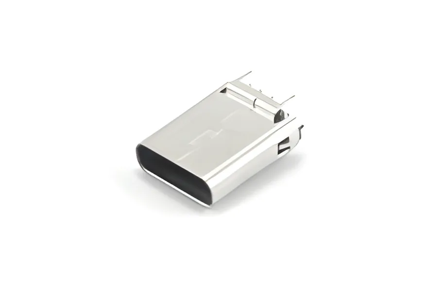
Terminal blocks provide a modular, reusable connection point where wires can be landed, tested, and replaced without cutting or splicing. They are the backbone of industrial control panels, power distribution systems, and building automation.
Screw Terminal Blocks
The traditional design. A screw clamp presses the wire against a metal bus bar. Screw terminals handle high currents reliably and are easy to inspect. The downside is that screws can loosen over time due to thermal cycling and vibration, requiring periodic retorquing.
Spring-Cage Terminal Blocks
A spring mechanism grips the wire without a screw. Spring-cage terminals are vibration-resistant, maintenance-free, and faster to wire. They have become the standard in European industrial automation (WAGO, Phoenix Contact style). Current ratings are comparable to screw terminals up to about 30 A.
Push-In Terminal Blocks
Push-in terminals allow a solid or ferrule-tipped stranded wire to be inserted directly without tools. They are the fastest to wire and are increasingly used in building automation and lighting panels. They are not ideal for fine-stranded wire without ferrules.
Barrier Terminal Strips
Barrier strips use raised walls between adjacent terminals to prevent accidental shorts. They are common in power supplies, audio equipment, and older industrial panels. They typically use screw termination and are available in high-current ratings.
| Terminal Block Type | Termination | Vibration Resistance | Wiring Speed | Typical Current |
|---|---|---|---|---|
| Screw Terminal | Screw clamp | Moderate | Slow | Up to 150 A+ |
| Spring-Cage | Spring | High | Fast | Up to 30 A |
| Push-In | Direct insertion | High | Fastest | Up to 20 A |
| Barrier Strip | Screw | Moderate | Slow | Up to 60 A |
Wire-to-Wire Connectors
Wire-to-wire connectors join two discrete wires or cable assemblies without a PCB or panel in the path. They are essential in harness-to-harness junctions, field-serviceable equipment, and any system where cable assemblies are built separately and mated during installation.
Inline Connectors
Inline connectors mate two wire ends in a straight-through configuration. They range from simple two-pin housings to high-density multipin connectors with polarization and locking features. Molex Mini-Fit, JST VH, and TE Mate-N-Lok are common series in this category.
Weatherproof Connectors
Weatherproof wire-to-wire connectors add seals, O-rings, and locking mechanisms to survive outdoor, marine, and underhood environments. They are rated by IP code — IP67 (submersible) and IP69K (high-pressure washdown) are common targets. CZT manufactures sealed wire-to-wire connectors for automotive and EV harness applications.
Quick-Disconnect Connectors
Quick-disconnects use a tab-and-receptacle design that mates and unmates by hand or with a simple pull. They are standard in appliance wiring, HVAC systems, and automotive accessories. Sizes range from 0.110" (2.8 mm) to 0.250" (6.3 mm) tab widths.
Wire-to-Board Connectors
Wire-to-board connectors terminate a discrete wire or cable onto a printed circuit board. They are one of the highest-volume wire connector types in electronics manufacturing, found in everything from consumer devices to automotive ECUs.
Header and Socket Pairs
The most common wire-to-board interface is a pin header soldered to the PCB mated with a crimp housing on the wire side. Pitch (pin spacing) ranges from 1.0 mm for compact electronics to 5.08 mm for power connections. Common series include Molex Micro-Fit (3.0 mm), JST XH (2.5 mm), and TE MTA (2.54 mm).
IDC Wire-to-Board Connectors
Insulation displacement connectors on the board side accept ribbon cable directly, eliminating the need to strip and crimp individual wires. They are standard for internal connections in computers, printers, and industrial controllers. The 2.54 mm pitch IDC header is ubiquitous.
FFC/FPC Connectors
Flat flexible cable (FFC) and flexible printed circuit (FPC) connectors are designed for ultra-thin, high-density connections. They use a ZIF (zero insertion force) or LIF (low insertion force) actuator to clamp the flat cable. Pitches go as fine as 0.3 mm. They are essential in laptops, smartphones, cameras, and automotive displays.
| Wire-to-Board Type | Pitch Range | Current per Pin | Key Advantage |
|---|---|---|---|
| Header / Socket | 1.0–5.08 mm | 1–13 A | Versatile, wide range of sizes |
| IDC (Ribbon Cable) | 1.27–2.54 mm | 1–3 A | No stripping or crimping needed |
| FFC / FPC | 0.3–1.25 mm | 0.5–1 A | Ultra-thin, high density |
Automotive Wire Connectors
Automotive environments are among the harshest for connectors: temperature extremes from -40 C to +125 C, constant vibration, exposure to oil, fuel, salt spray, and water. Automotive wire connectors must meet these demands while remaining field-serviceable.
Deutsch-Style Connectors
Deutsch DT, DTM, and DTP series connectors are the industry standard for heavy-duty automotive and off-highway equipment. They feature machined contacts, silicone seals, and a robust thermoplastic housing. DT series handles 13 A per pin on 20–16 AWG wire. DTP series handles 25 A on 12–8 AWG.
Weatherpack Connectors
Delphi (now Aptiv) Weatherpack connectors are widely used in GM and aftermarket automotive wiring. They use a tower-and-shroud design with individual wire seals. They are cost-effective for moderate-density applications and handle up to 20 A per circuit.
Metri-Pack Connectors
Metri-Pack is another Aptiv family, available in 150, 280, 480, and 630 series (the number refers to the terminal blade width in hundredths of an inch). Metri-Pack 150 is used for signal circuits; Metri-Pack 630 handles up to 46 A for power distribution.
Sealed Connector IP Ratings
The IP (Ingress Protection) rating tells you exactly what a sealed connector can withstand. For automotive wire connectors, IP67 is the minimum for underbody and engine bay applications. IP69K is required for components exposed to high-pressure steam cleaning.
| IP Rating | Dust Protection | Water Protection |
|---|---|---|
| IP54 | Dust-protected | Splash-proof |
| IP67 | Dust-tight | Submersible (1 m, 30 min) |
| IP68 | Dust-tight | Continuous submersion |
| IP69K | Dust-tight | High-pressure, high-temp washdown |
CZT produces a full range of sealed automotive connectors rated IP67 through IP69K, designed and tested to USCAR and LV214 standards.

Insulation Displacement Connectors (IDC)
Insulation displacement connectors eliminate the wire-stripping step entirely. The connector has a sharp metal blade that slices through the wire insulation during termination, making direct contact with the conductor. This creates a gas-tight connection similar to a crimp.
How IDC Works
The wire is pressed into a slot that is narrower than the wire's insulation diameter. The slot edges cut through the insulation and bite into the copper conductor. The slot geometry is designed to create a controlled deformation that maintains contact force over time.
Advantages of IDC
IDC termination is fast — a single press seats the wire. It requires no stripping, no crimping tool calibration, and no solder. This makes it ideal for high-volume production and field termination of multi-conductor cables. Telecom punchdown blocks (110 and Krone style) are IDC connections.
IDC Applications
IDC is standard in structured cabling (Cat5e/Cat6 keystone jacks and patch panels), ribbon cable assemblies, telecom cross-connects, and some automotive harness applications. The limitation is wire gauge range — most IDC connectors are designed for 22–26 AWG solid or stranded wire.
Wire Connector Selection Guide
Choosing the right wire connector comes down to matching the connector's ratings to the application's demands. The table below provides a decision framework.
| Selection Criteria | What to Check | Why It Matters |
|---|---|---|
| Current Rating | Connector datasheet vs. circuit max current | Undersized connectors overheat and fail |
| Wire Gauge (AWG) | Connector barrel/slot size vs. wire size | Mismatch causes poor contact or wire damage |
| Voltage Rating | Connector dielectric rating vs. system voltage | Prevents arcing and insulation breakdown |
| Temperature Range | Connector material rating vs. ambient + self-heating | Plastic housings degrade outside rated range |
| Moisture / IP Rating | IP code vs. installation environment | Corrosion is the leading cause of connector failure |
| Vibration | Locking mechanism, contact retention force | Automotive and industrial environments demand positive locks |
| Mating Cycles | Rated cycles vs. expected service life | Contacts wear with each mate/unmate cycle |
| Wire Termination | Crimp, solder, IDC, screw | Must match production process and field service needs |
| Cost | Per-connection cost at production volume | Over-specifying wastes money; under-specifying causes failures |
For automotive applications, start with the environmental requirements (temperature, sealing, vibration) and work backward to the connector family. For industrial panel wiring, start with the current rating and termination method. For electronics, start with the pitch and board footprint.
When in doubt, consult the manufacturer's application guide. CZT provides engineering support for connector selection across automotive and industrial applications.
Wire Connector Best Practices
Even the best connector fails if it is installed incorrectly. These practices apply across all types of wire connectors.
Proper Crimping
Use the correct die set for the terminal. A crimp that is too loose creates high resistance; a crimp that is too tight cuts wire strands. Calibrate crimp tools per the manufacturer's specification. For production environments, use pull-test and cross-section analysis to validate crimp quality.
Wire Gauge Matching
Never force an oversized wire into a connector barrel, and never use an undersized wire that does not fill the barrel. The connector datasheet specifies the acceptable wire gauge range. Using a wire outside that range voids the connector's current and mechanical ratings.
Strain Relief
Every connector termination needs strain relief to prevent flexing at the junction point. This can be a cable clamp, a heat-shrink boot, a backshell, or the connector housing's built-in strain relief feature. Without it, repeated flexing will fatigue and break the conductor at the termination.
Environmental Sealing
For any outdoor, underhood, or washdown application, use sealed connectors with the appropriate IP rating. Seal all unused cavities with blanking plugs. Verify that wire seals are the correct size for the wire gauge — an oversized seal leaks, and an undersized seal damages the wire insulation.
Inspection and Testing
After termination, inspect every connection. For crimp terminals, verify that the wire is visible in the inspection window and that the insulation grip is properly seated. For screw terminals, verify torque. For sealed connectors, perform a tug test on each wire to confirm contact retention.
FAQ
What are the most common types of wire connectors?
The most common types of wire connectors are crimp terminals (ring, spade, butt), terminal blocks (screw and spring-cage), wire-to-board headers, and quick-disconnect tabs. In automotive applications, sealed multipin connectors like Deutsch DT and Metri-Pack are standard. The right type depends on your current rating, environment, and whether the connection needs to be serviceable.
What is the difference between a crimp connector and a solder connector?
A crimp connector uses mechanical deformation to join wire to terminal. A solder connector uses molten metal alloy. Crimping is faster, more consistent in production, and performs better under vibration. Soldering provides a lower-resistance joint but is slower, introduces heat risk, and can crack under repeated thermal cycling or vibration. Most automotive and industrial standards specify crimping over soldering.
How do I choose the right wire connector for outdoor use?
Start with the IP rating. IP67 is the minimum for outdoor connectors exposed to rain and temporary submersion. IP69K is required for high-pressure washdown environments. Beyond the IP rating, check the connector's temperature range, UV resistance of the housing material, and corrosion resistance of the contacts (tin, gold, or nickel plating). Sealed automotive wire connectors are often the best choice for harsh outdoor applications.
Can I use automotive connectors for industrial applications?
Yes, and it is often a smart choice. Automotive connectors are designed for vibration, temperature extremes, and moisture — conditions that many industrial environments share. Deutsch-style connectors, for example, are widely used in agricultural equipment, marine systems, and factory automation. The key is to verify that the connector's electrical ratings (current, voltage) match your industrial circuit requirements.
What wire gauge do I need for my connector?
Wire gauge is determined by the circuit's current draw and the acceptable voltage drop over the wire run length. Once you know the wire gauge, select a connector rated for that gauge. Most connector datasheets list an AWG range (e.g., 18–14 AWG). Using wire outside the specified range results in unreliable terminations. For help sizing wire and connectors for your application, contact CZT engineering.
Partner with CZT for Wire Connector Solutions
CZT manufactures automotive-grade wire connectors, terminal blocks, and custom wire harness assemblies. With 30+ years of experience, IATF 16949 certification, and production capacity serving 60+ countries, we deliver the quality and volume your projects demand.