A threaded hole or insert in a die-cast enclosure should be accepted as part of a fastening joint. Thread engagement alone does not establish retention, and a successful fit with one screw does not prove the delivered joint meets the product's mechanical and service requirements.

Figure 1. CZT MINI SAS structural component. Mounting and fastening features must be defined by the selected component drawing; no thread specification is inferred. CZT source · Original image.
Specify the actual fastening arrangement
Identify the screw, washer, mating component and installation method. Define thread designation, usable engagement, entry condition and any coating or insert. For a blind hole, distinguish total drilled depth from usable thread and clearance to the screw tip. A screw can feel tight because it has bottomed without properly clamping the assembly.
If an insert is proposed, record its type, location and installation process. Do not assume that two inserts with similar threads are interchangeable in the casting. The surrounding geometry and the way installation loads enter the part matter.
Agree on separate acceptance checks
| Check | Purpose |
|---|---|
| Thread or gauge inspection | Confirm the defined thread condition |
| Depth and entry | Verify engagement and access without bottoming |
| Joint assembly | Confirm seating with the intended screw and mating part |
| Retention evaluation | Assess the project-defined mechanical requirement |
| Service cycling, where needed | Evaluate repeated removal and installation |
Select loads and acceptance criteria from the assembly requirements. This article does not assign a generic tightening torque or pull-out value to CZT casting references.
Connect the test to the delivered condition
Record whether threads are cast, machined or created through an insert. Include the material, finish and any lubricant involved in the fastening operation. If a test changes these conditions, explain why its result applies to the production joint.
Inspect the part after the mechanical evaluation. A fastener may remain attached while the surrounding casting, insert or mounting seat is damaged. Photographs and relevant dimensional checks can help distinguish the failure mechanism from the headline load result.
Use the CZT die-casting component page to request the actual thread and mounting drawing for a candidate. A structural-part label is a starting reference, not evidence of a particular thread-strength capability.
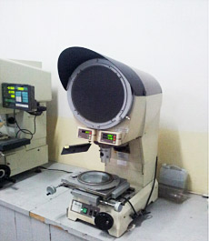
Figure 2. CZT optical-inspection equipment. Measurement-method context for inspecting defined features, not proof of thread strength or an insert test. CZT source · Original image.
Transfer the acceptance method into production
Define which checks belong in incoming inspection, process control and periodic verification. Destructive retention testing cannot simply be treated like a non-destructive gauge check on every delivered component. Agree on sample identity and lot relationships so the evidence can be interpreted.
Keep assembly instructions aligned with the approved joint. A later change to screw length, coating, washer or tightening equipment can affect the interface even when the casting part number is unchanged. Review that change against the original joint requirements before relying on the previous approval.
Connect this review to CZT product information
Start with the relevant CZT product family and provide the original interface reference or controlled drawing. Ask which configurations and supporting documents are available for the task described here. Confirm the mating arrangement, required features and project conditions before choosing an orderable part.
Browse the relevant product family · View catalog resources
Discuss a drawing, sample or quotation
Share the part or family reference, current drawing revision, operating conditions and quantities. Include the specific checks described in this article so the inquiry identifies both the component and the evidence needed for your decision. Confirm sample availability and the proposed scope with the supplier.