A high-density fiber-panel cutout must be reviewed against the selected adapter's mounting and service geometry. Matching a connector-family name does not establish the opening dimensions, latch engagement or permissible panel thickness. Use a controlled installed drawing and a representative panel sample before committing the production cutout.
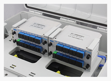
Figure 1. Official optical-distribution panel illustrates adapter openings and service density; dimensions for a proposed LC or MPO adapter must come from its own drawing. CZT source · Original image.
Define the adapter and panel interface
Identify the exact adapter construction, including any flange, retaining clip or other mounting feature. Record the panel material, finished thickness, coating and cutout edge condition. The adapter contacts the finished panel, so the coating process belongs in the dimensional stack.
CZT's fiber-optic product family is a route for an interface consultation. Its specifically identified SC-to-FC cable listing does not establish a panel adapter construction or an LC/MPO cutout. Request an actual available part proposal and drawing for the intended panel interface.
Check engagement at the tolerance extremes
Review the features that locate and retain the adapter. Determine whether the minimum and maximum finished panel thicknesses permit the intended engagement. Check whether burrs, paint or local distortion interfere with seating.
Do not enlarge a cutout simply because a first sample is difficult to insert. Identify whether the cause is the opening, edge condition, adapter dimension or insertion method. A larger opening may remove the locating or retention function needed by the installed part.
A panel-interface checklist
| Feature | Check to complete |
|---|---|
| Opening profile | Controlled dimensions, datum and orientation |
| Finished thickness | Panel plus relevant surface finish |
| Retention | Latch or fastener engagement across tolerances |
| Front clearance | Connector insertion, latch and finger or tool access |
| Rear clearance | Cable routing, support and permitted bends |
| Removal method | Service sequence without damaging adjacent ports |
Use an installed section where a front view hides the clip or latch relationship. A component can appear flush while its retention feature is only partly engaged.
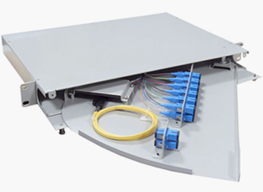
Figure 2. Official distribution unit illustrates rear fiber routing and assembly access, complementing the front-panel cutout review without specifying an adapter footprint. CZT source · Original image.
Validate a fully populated panel
Fit the actual adapters, intended connector bodies and cable boots into representative openings. Check insertion and removal in the middle of a populated row, where neighboring parts restrict access. Record the parts and panel conditions used in the trial.
A hypothetical adapter may fit a thin prototype panel but fail to latch in the thicker coated production panel. The correct action is to resolve the specified interface and tolerance range, not to force the part into the opening or accept a partially seated state.
Inspect the panel opening after the production finishing process. A prototype cutout measured before coating does not establish the finished opening. Keep the acceptance datum and edge requirement visible to the fabricator and receiving inspector.
Preserve the approved cutout, finished-thickness requirement and sample-review record with the panel drawing. Revisit them after changing adapter supplier, coating, panel material or mounting method. This gives manufacturing a defined interface and keeps port-density decisions connected to actual assembly and service performance.
Connect this review to CZT product information
For LC, MPO, polish or polarity requirements, start with the fiber-optic product family. The available SC-to-FC assembly record is a different interface and is not presented here as a matching LC or MPO part. Ask CZT to confirm the exact configuration and available documentation.
Browse the relevant product family · View catalog resources
Discuss a drawing, sample or quotation
Share the part or family reference, current drawing revision, operating conditions and quantities. Include the specific checks described in this article so the inquiry identifies both the component and the evidence needed for your decision. Confirm sample availability and the proposed scope with the supplier.
Request a technical review or quotation
For broader context, read the related selection guide.