An optical-link budget should account for the complete path between transmitter and receiver, including fiber, connections, splices and a justified design margin. Keep the component specifications and their operating conditions attached to each allowance. A budget is a design calculation; an installed-link measurement is separate evidence that the actual path meets the requirement.
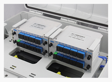
Figure 1. Official optical-distribution enclosure example illustrates the intermediate connections that should be counted when documenting a complete optical-link loss budget. CZT source · Original image.
Establish the endpoint limits
Obtain the exact transmitter and receiver specifications at the intended rate and operating conditions. Use the stated power definitions consistently. Also check any upper receive-power limit, rather than assuming that a shorter or lower-loss path can never create an issue.
Cisco's optical attenuation and measurement explanation distinguishes optical power from relative loss. Preserve that distinction in the worksheet: power in dBm and path loss in dB should not be treated as interchangeable labels.
Count the actual interfaces
Draw every connection and splice, including patch panels and equipment-side leads. Confirm whether a specified loss allowance refers to one component, one mated connection or an entire assembly. Otherwise, the same interface can be omitted or counted twice.
Record fiber length and the applicable attenuation input at the operating wavelength. Identify where allowances come from: a controlled component specification, an engineering requirement or an actual measurement. Do not insert a favorable typical value where a design-limit value is required.
A hypothetical budget example
These numbers are invented solely to show the arithmetic; they are not CZT ratings or a design recommendation.
| Item | Example allowance |
|---|---|
| Available endpoint budget | 8.0 dB |
| Fiber path | 2.0 dB |
| Four mated connections combined | 1.2 dB |
| Splices combined | 0.4 dB |
| Reserved margin | 2.0 dB |
| Remaining example allowance | 2.4 dB |
The design owner must justify each actual allowance and the required margin. A positive arithmetic remainder alone does not establish host compatibility, dispersion performance or every other link requirement.
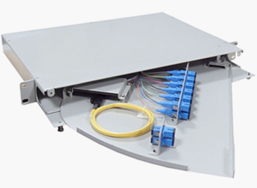
Figure 2. Official splice-and-distribution unit illustrates a separate assembly boundary; identify actual splices and mated connections before allocating loss allowances. CZT source · Original image.
Verify the installed path
Measure the completed link using the specified method, wavelength and reference arrangement. Keep the connection inventory beside the result so that unexpected loss can be investigated by location. Revisit the budget when adding a patch panel or changing a connector assembly.
CZT's fiber-optic product family is a consultation route for interface requirements. The catalog's identified SC-to-FC patch-cable example is not an LC, MPO or unspecified optical-port substitute; suitability requires its own interface review.
Keep planned repair or expansion allowances distinct from measured installed loss. This makes it clear whether remaining margin has been deliberately reserved or merely left unused. When an extra panel is added, update the connection inventory and obtain the corresponding measurement instead of continuing to quote the original worksheet unchanged.
Store the calculation, endpoint data and installed test result together. That makes later changes reviewable and prevents a successful power-up from becoming the only evidence that an optical path has sufficient operating margin.
Connect this review to CZT product information
For LC, MPO, polish or polarity requirements, start with the fiber-optic product family. The available SC-to-FC assembly record is a different interface and is not presented here as a matching LC or MPO part. Ask CZT to confirm the exact configuration and available documentation.
Browse the relevant product family · View catalog resources
Discuss a drawing, sample or quotation
Share the part or family reference, current drawing revision, operating conditions and quantities. Include the specific checks described in this article so the inquiry identifies both the component and the evidence needed for your decision. Confirm sample availability and the proposed scope with the supplier.
Request a technical review or quotation
For broader context, read the related selection guide.