Heat-sink base flatness and thermal-pad thickness should be reviewed together because the interface must accommodate the assembled gap while maintaining the intended contact condition. Specifying a thick pad without examining the geometry can increase thermal resistance, while specifying a very thin pad can leave an uneven interface poorly supported.
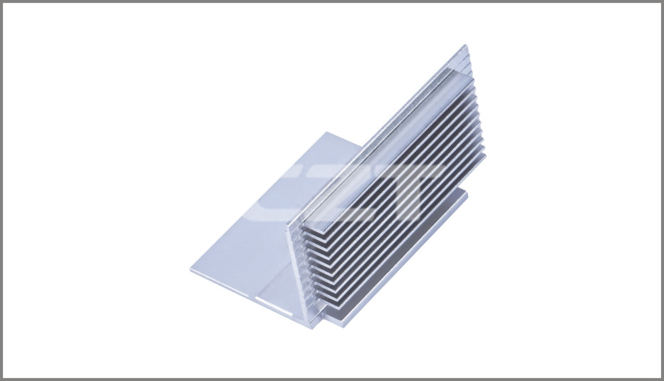
Figure 1. CZT SRQ-HJ-01 heat sink. The base and fin geometry make the interface review concrete; actual flatness and TIM requirements require drawings and measurements. CZT source · Original image.
Define the assembled gap
Start with the device reference plane, heat-sink mounting plane, fastener locations and any intervening spacers. Include tolerances, board deflection and the expected effect of tightening. The nominal gap is only one point in this stack-up. A design must also account for the largest and smallest plausible gaps across the heat-transfer area.
Distinguish overall flatness from local roughness and from the parallelism of the mounted assembly. A flat base can still sit at an angle if the standoffs or mounting surfaces differ in height. A single center measurement will not reveal that condition.
Review the interface as a system
| Review item | Evidence to request | Question to resolve |
|---|---|---|
| Base shape | Controlled drawing and measurement map | Is the specified area flat in its delivered condition? |
| Gap range | Tolerance analysis at relevant locations | Where will compression be highest and lowest? |
| Pad behavior | Supplier data for thickness and compression | Does the selected material cover that range? |
| Mounting load | Fastener or spring arrangement | Can the assembly apply load without damaging the device? |
| Rework | Removal and replacement method | Does service change thickness, alignment or contact? |
A pad's nominal thermal conductivity is not a complete description of interface performance. The delivered thickness, compressed thickness, contact condition and heat-source area all affect the result. Use the material supplier's applicable data rather than comparing conductivity figures in isolation.
Keep the drawing measurable
Identify which base region is thermally functional and how it will be inspected. If anodizing, machining or an applied interface changes that surface, define whether measurements apply before or after the operation. Record the datum arrangement and the measurement support so the part is not forced flat by an inspection fixture in a way the real assembly will not reproduce.
For a CZT heat-sink drawing review, provide the mating component and mounting arrangement alongside the sink outline. A model label alone cannot establish an appropriate flatness tolerance or compatible pad.
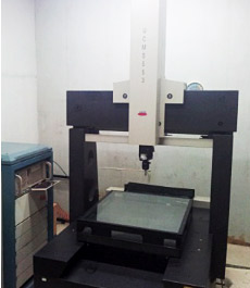
Figure 2. CZT coordinate-measurement equipment. Dimensional inspection provides context for flatness and stack-up verification; no base-flatness result is demonstrated. CZT source · Original image.
Validate the assembled condition
Build representative combinations that cover the expected tolerance range. Confirm seating and fastener engagement, then measure thermal performance with the intended load and environment. If inspection uses pressure-indicating media or another contact-mapping technique, ensure that it does not alter the final thermal stack.
Keep the approved drawing, material designation, mounting procedure and test configuration together. Reassess them when a pad supplier, spacer height or base-finishing process changes. An unchanged heat-sink part number does not make those changes thermally invisible, and the purchasing specification should make the controlled interface clear.
Connect this review to CZT product information
Start with the relevant CZT product family and provide the original interface reference or controlled drawing. Ask which configurations and supporting documents are available for the task described here. Confirm the mating arrangement, required features and project conditions before choosing an orderable part.
Browse the relevant product family · View catalog resources
Discuss a drawing, sample or quotation
Share the part or family reference, current drawing revision, operating conditions and quantities. Include the specific checks described in this article so the inquiry identifies both the component and the evidence needed for your decision. Confirm sample availability and the proposed scope with the supplier.