RJ45 center taps must be identified by which side of the isolation transformer they belong to and by their function in the selected PHY and PoE architecture. A center-tap pin is not a universal supply or ground connection. Copying its treatment from an unrelated Ethernet design can connect the correct-looking connector to the wrong circuit.
Begin with the internal schematic of the candidate in the CZT RJ45 integrated magnetics family, then trace every center-tap node to the approved system schematic.
Distinguish the two sides of the transformer
Label the PHY side and cable side explicitly. The PHY-side network follows the PHY manufacturer's interface requirements. Depending on the device, that can involve a particular bias or decoupling arrangement. Cable-side center taps can form part of a PoE power path, but their use depends on the actual powered-device or power-sourcing architecture.
Do not use the symbol's position on the page as proof of orientation. Confirm the winding labels and pin functions. Drawings can present a bottom view, mating view or simplified internal schematic with different visual directions.
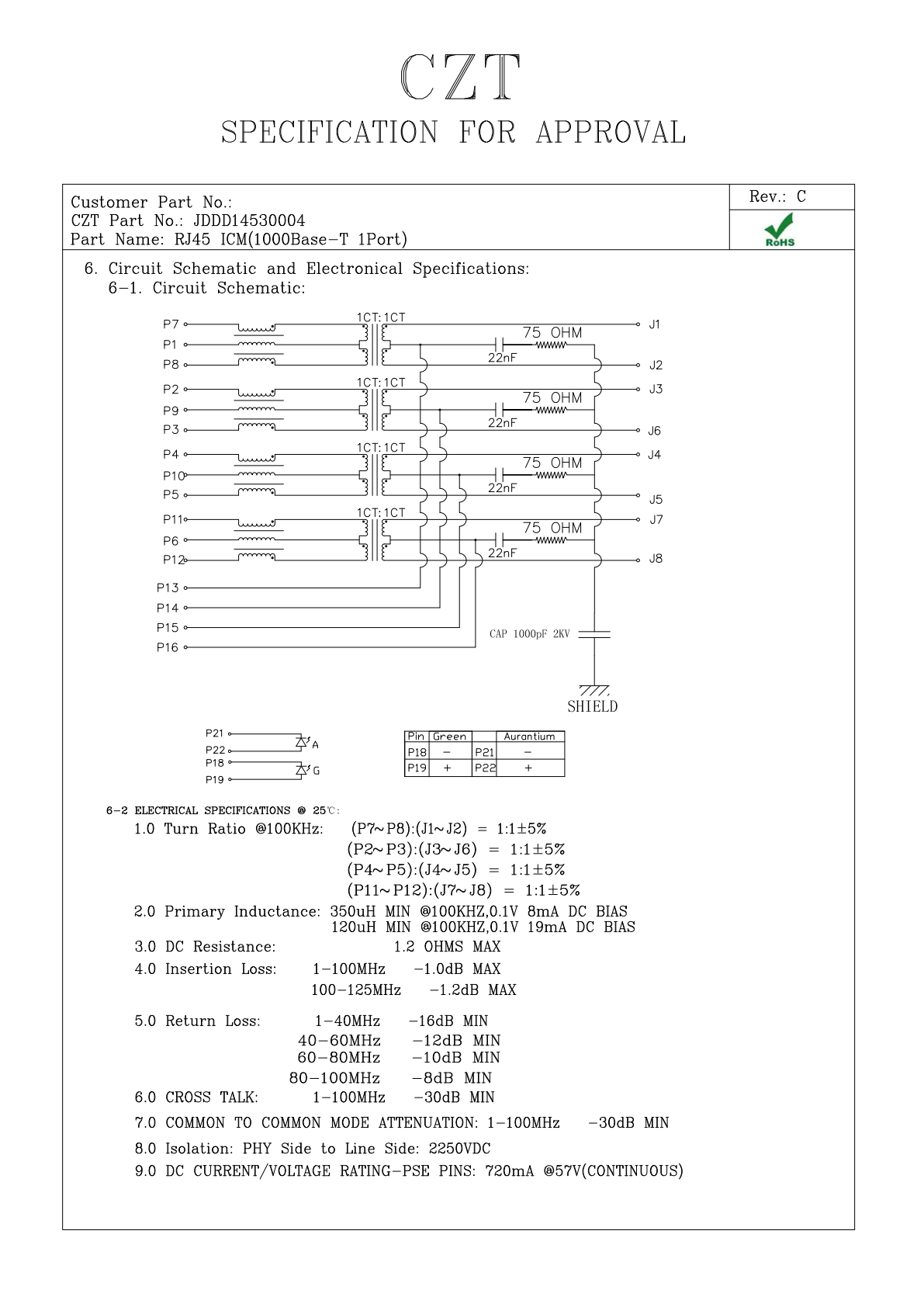
Figure 1. JDDD14530004: internal circuit and electrical specification fields from the official manufacturer specification, PDF page 6. CZT source · Original PDF, page 6.
Map power and data as separate paths
For each pair, trace the differential signal through the winding. On a second copy of the schematic, mark the DC path associated with the intended PoE configuration. This separates two questions that are often accidentally combined: whether the data circuit is suitable and whether the power path is supported.
The power-path drawing should include the relevant bridge, controller or injection network, not stop at the connector pin. It should also identify any internal ties in the ICM. These affect which nodes are available to the board designer.
Use a node-by-node worksheet
| Center-tap node | Questions to close |
|---|---|
| PHY-side pair A | Which reference-design instruction controls this node? |
| PHY-side remaining pairs | Are these independent, internally joined or unused? |
| Cable-side powered pairs | Where does DC enter or leave the interface? |
| Unused accessible taps | What treatment does the approved circuit specify? |
| Shield and termination nodes | Are they clearly distinguished from center taps? |
Add the connector pin, schematic net and drawing revision beside each answer. A completed worksheet is more useful than a statement that a part is “PoE ready,” because it shows the intended implementation.
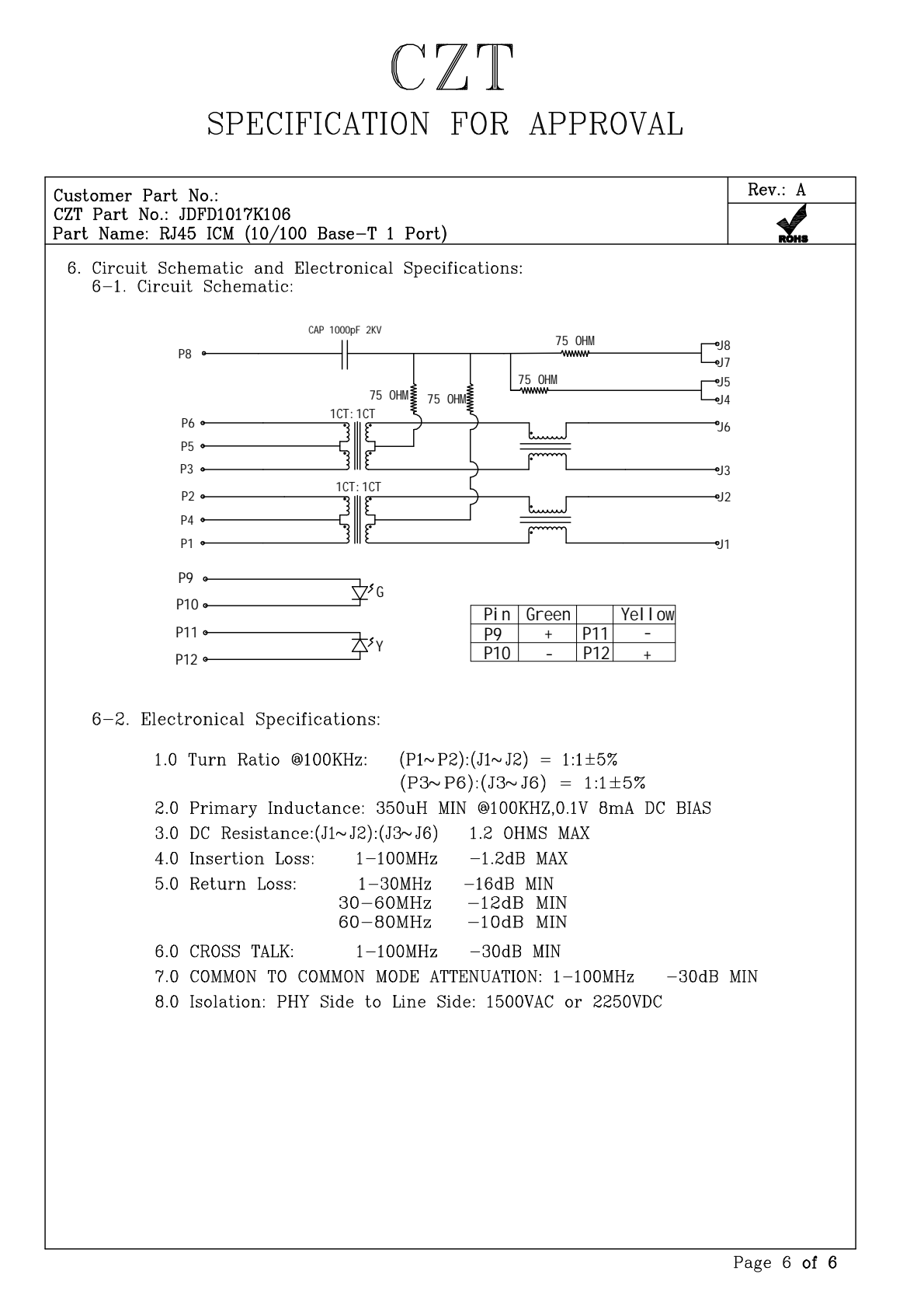
Figure 2. JDFD1017K106: internal circuit and electrical specification fields from the official manufacturer specification, PDF page 6. CZT source · Original PDF, page 6.
Review changes before energizing a prototype
Consider a hypothetical redesign from a non-PoE port to a powered port. Retaining the same enclosure and footprint does not establish that the existing connector exposes the required cable-side nodes or supports the proposed operating conditions. The circuit and component requirements must be reviewed together.
Continuity checks can help verify pin mapping on an unpowered sample, but they do not establish isolation performance or operating suitability. Plan those evaluations separately using appropriate equipment and approved test methods.
A clear center-tap review ends with an annotated internal circuit, a corresponding system netlist and ownership of any open questions. That documentation makes a later connector change easier to evaluate without repeating the entire investigation.
Connect this review to CZT product information
Start with the relevant CZT product family and provide the original interface reference or controlled drawing. Ask which configurations and supporting documents are available for the task described here. Confirm the mating arrangement, required features and project conditions before choosing an orderable part.
Browse the relevant product family · View catalog resources
Discuss a drawing, sample or quotation
Share the part or family reference, current drawing revision, operating conditions and quantities. Include the specific checks described in this article so the inquiry identifies both the component and the evidence needed for your decision. Confirm sample availability and the proposed scope with the supplier.
Request a technical review or quotation
For broader context, read the related selection guide.