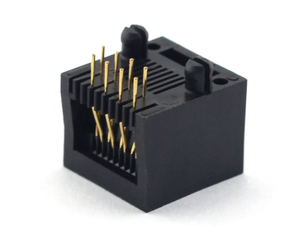
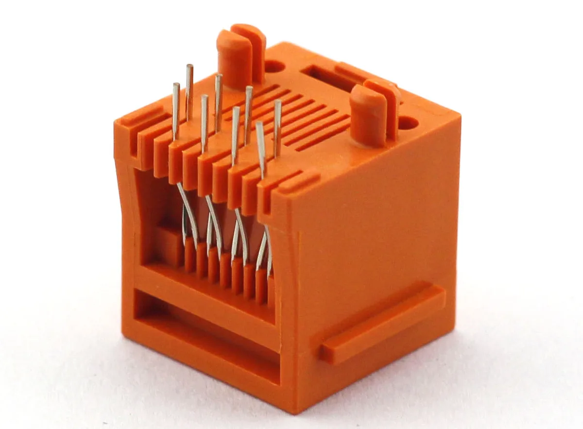
RJ45 retention tabs and panel support should create an intentional path for insertion, removal and cable loads. The electrical contacts and solder joints should not be treated as unspecified mechanical fasteners simply because the connector currently stays in place.
Use a candidate from the CZT modular jack range and inspect its actual mounting features. Some constructions include flanges, pegs or shell features that require different PCB and enclosure details.
Trace the load into the assembly
Start at the mating plug and follow the load through the jack body, retention features, PCB and enclosure supports. Consider insertion, latch release and cable movement separately. Their directions and points of application can differ.
Identify which surfaces are intended to touch the panel and which require clearance. Unplanned contact can distort the assembly or change how loads are shared, while a missing intended support can leave the board carrying more load than expected.
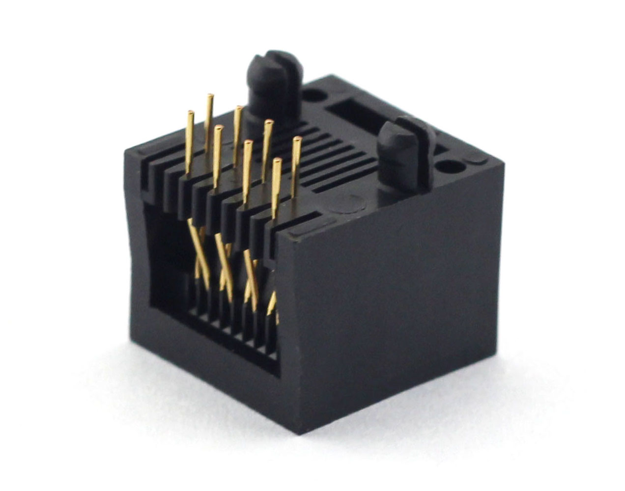
Figure 1. E52QWY-1093-5 socket construction from CZT's original catalog. CZT source · Original image.
Review holes, tabs and seating together
Check the mounting-hole dimensions, tab geometry, locating features and allowed seating position on the controlled drawing. Do not enlarge holes or modify tabs merely to make a prototype easier to assemble without reviewing the effect on retention.
For a soldered shell feature, include its joint requirements and inspection access. For a locating peg, determine whether its role is positioning, retention or another specified function. Appearance alone does not define its responsibility.
Build a mechanical review table
| Feature | Required decision |
|---|---|
| Shell tab | Connection, solder requirement and load role |
| Locating feature | Hole fit, seating and intended function |
| Flange or panel surface | Contact condition and tolerance |
| PCB support | Distance, stiffness and mounting arrangement |
| Cable route | Expected direction of external movement |
| Validation | Applied conditions and inspection after loading |
Use project-defined mechanical requirements rather than inventing a universal force limit. Record the actual mating accessory used in the evaluation.
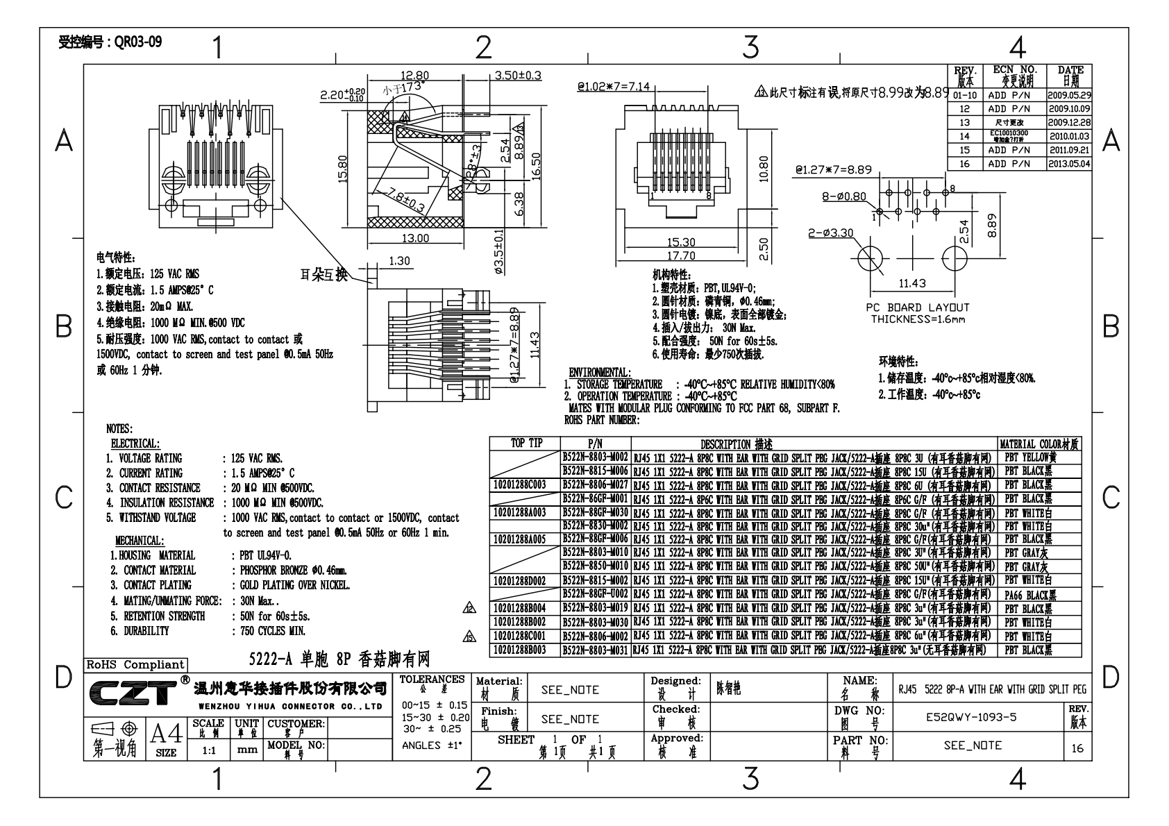
Figure 2. Official E52QWY-1093-5 drawing, preserving the manufacturer's model and revision markings. CZT source · Original PDF, page 1.
Test the intended assembly
Evaluate the connector on the representative board and enclosure, not only on an unsupported test coupon. Inspect for movement, damage, solder changes and functional effects after the agreed mechanical sequence.
In a hypothetical instrument, a panel opening might provide support only when the PCB is at one end of its mounting tolerance. The nominal assembly can look satisfactory while another allowed position leaves the jack unsupported. Reviewing the tolerance extremes reveals that issue.
Preserve the support detail
Release the connector drawing, PCB footprint and relevant enclosure section together. If a substitute changes tab length, flange geometry or shell position, revisit the mechanical path even if the signal footprint matches.
This gives both engineering and purchasing a concrete criterion for compatibility: the reviewed assembly must transfer its expected loads without relying on an accidental fit or an undocumented support condition.
Connect this review to CZT product information
Catalog references to discuss are listed below. Use the identifiers to request the current drawing and confirm the configuration required by your application.
| Catalog reference | Product information | Drawing record | Reference inquiry |
|---|---|---|---|
| E52QWY-1093-5 | 5222-A 8-position jack with listed flange and peg options, E52QWY-1093-5 | Listed PDF | Ask about this reference |
| E52QWY-1193-2 | 5222 8-position jack with listed flange and peg options, E52QWY-1193-2 | Listed PDF | Ask about this reference |
A catalog drawing reference is a starting document, not a substitute for reviewing its revision, options and suitability for the complete assembly.
Browse the relevant product family · View catalog resources
Discuss a drawing, sample or quotation
Share the part or family reference, current drawing revision, operating conditions and quantities. Include the specific checks described in this article so the inquiry identifies both the component and the evidence needed for your decision. Confirm sample availability and the proposed scope with the supplier.
Request a technical review or quotation
For broader context, read the related selection guide.