Why socket catalogs are easy to misread
Socket connector requests often begin with a short phrase: RJ45 socket, network socket, coupler, or keystone jack. Those phrases are useful for a first conversation, but they are not precise enough for a drawing match.
The reason is simple: a socket catalog usually mixes four different layers.
- Board-mounted sockets that solder directly to the PCB.
- Pre-wired socket assemblies that connect a board or harness to an enclosure.
- Pass-through couplers that extend or adapt an interface.
- Network infrastructure accessories such as keystone jacks, surface boxes, IDC blocks, and patch panels.
Treating all four as the same product category creates RFQ noise. A sourcing team may ask for an RJ45 socket, while engineering actually needs a shielded SMT board jack. Or the installation team may need a CAT6 keystone module, while the buyer sends a PCB jack drawing.
Start with the mounting layer
The fastest way to narrow a socket request is to ask where the connector lives.
| Mounting layer | Typical catalog family | What it solves |
|---|---|---|
| PCB | PCB Jack, SMT RJ45, Offset RJ45 | Ethernet or telephone interface mounted directly on equipment boards |
| Cable / harness | Wired Jack, socket with cable | Internal routing between board, harness, and enclosure |
| Panel / pass-through | Coupler, RJ45/RJ11 adapter | Field-accessible extension or interface conversion |
| Structured cabling | Keystone, face plate, surface box, IDC block, patch panel | Installation-side cabling, telecom rooms, wall outlets, and patching |
Once the layer is known, the model family becomes much easier to compare.
Wired jack assemblies
Wired jack assemblies are useful when the Ethernet or telephone port cannot sit directly on the PCB edge. They provide a factory-terminated socket plus cable or lead routing so the enclosure, panel, or internal harness can drive the port location.
From the extracted socket catalog, the wired-jack family includes examples such as YH-119 623K left, YH-120 616EN, YH-121 623K right, YH-122 616E-B, YH-123 616E-B insert, YH-124 RJ12 socket 6P, and YH-125 RJ45 socket 8P.
For RFQ, confirm:
- Socket type: RJ45, RJ12, RJ11, 6P, 8P, or other modular interface.
- Cable exit direction: left, right, straight, or custom.
- Housing style: insert, bracket, panel-mount, flanged, or compact body.
- Cable details: length, wire gauge, jacket, shielding, free-end termination.
- Strain relief and vibration expectations.
PCB jack families
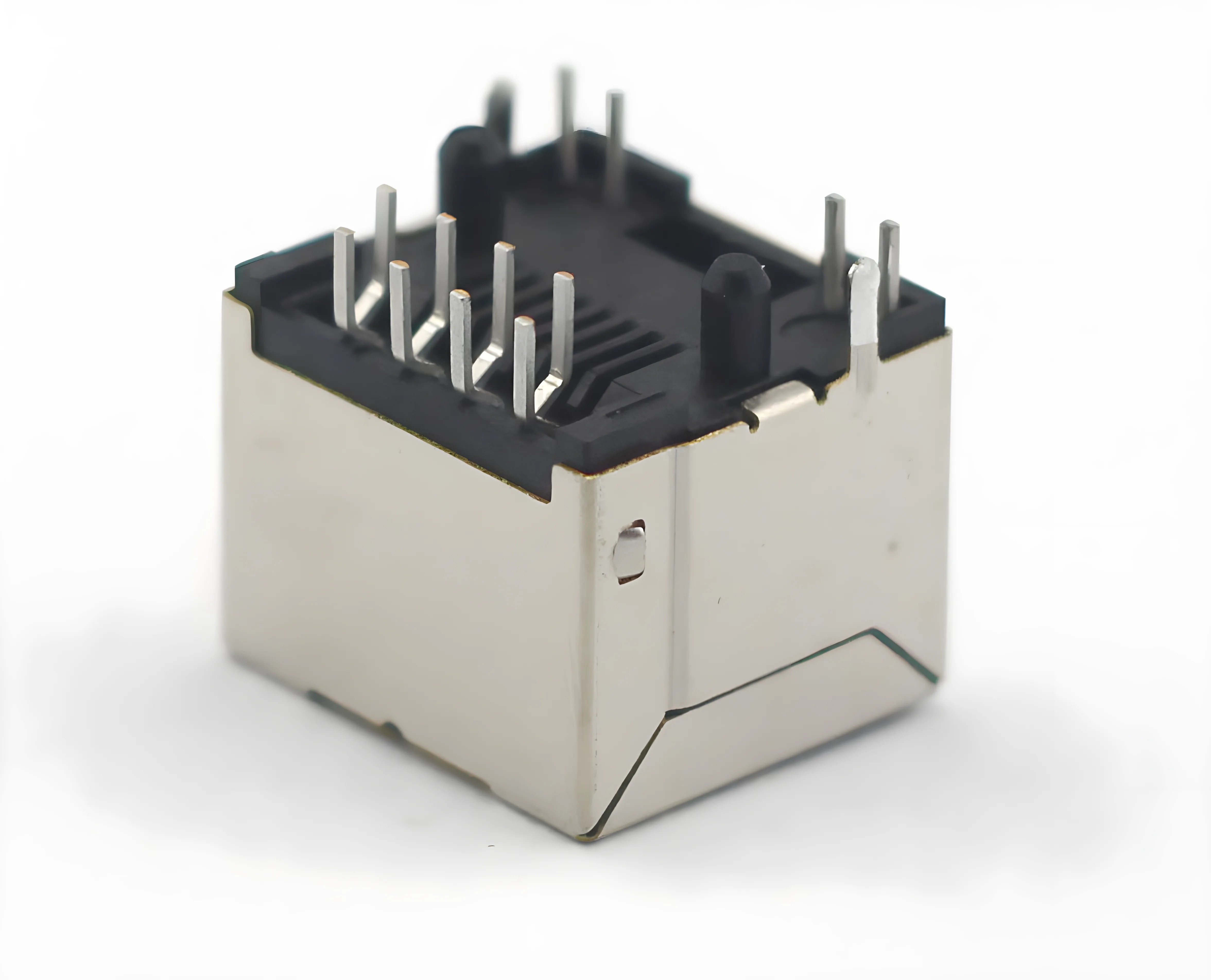
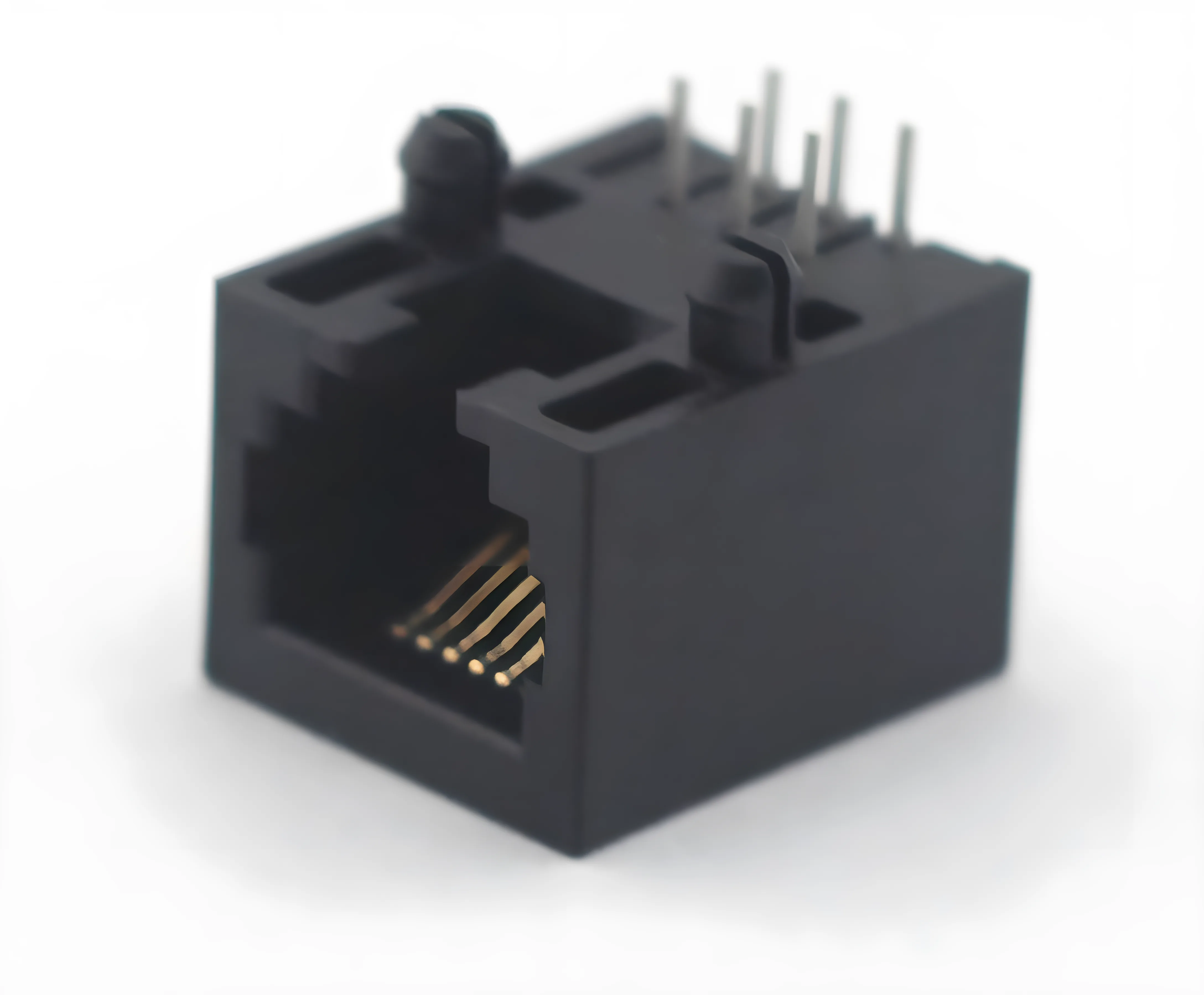
PCB jacks are component-level sockets. They are selected by electrical interface and mechanical footprint, not only by the word socket.
The catalog includes 51, 52, 53, 55, and 56 series families with examples such as 5222 4P, 5222 6P, 5222 8P, 5224 LED, 5321 SMT, 5521, 5621, and 5622 variants. These families cover 4P, 6P, 8P, and 10P styles, with shielded or unshielded housings, flanged or unflanged options, LED options, and different contact geometries.
Key selection checks:
- Pin count and wiring: 4P, 6P, 8P, 10P, 8P8C, or customer-specific.
- Board attachment: through-hole, SMT, hybrid, crimp, or press/contact style.
- PCB thickness and tail engagement.
- Shield, LED, flange, ear, or panel-retention needs.
- Contact plating and mating-cycle requirement.
- Height and enclosure clearance.
Offset and SMT RJ45 sockets
Offset RJ45 sockets solve a mechanical problem: the desired port location does not line up with a standard connector body. This happens when enclosure openings, adjacent ports, transformers, mechanical ribs, or cable exits constrain the PCB.
The extracted catalog references YH-OFFSET-01 RJ45 1X3S CAT5E 8P8C, YH-OFFSET-02 RJ45 1X1S CAT5E 8P8C, YH-OFFSET-03 RJ45 1X4S CAT5E 8P8C 30U, and additional 8P8C offset variants.
SMT RJ45 sockets solve a process and footprint problem. Examples include YH-SMT-01 5227 8P8C SMT, YH-SMT-02 616SMT, YH-SMT-03 623 SMT, YH-SMT-06 5321 8P SMT, and YH-SMT-13 RJ45 1X1 SMT 8P8C-B.
When choosing offset or SMT sockets, send the PCB drawing early. The important details are pad layout, keep-out area, reflow process, shield grounding, port centerline, and enclosure opening.
Couplers and network accessories
Couplers are not a substitute for PCB jacks. They are pass-through or adaptation components used at the cabling layer. The socket catalog includes YH-COU-16 RJ45, YH-COU-18 CAT5E, YH-COU-20 CAT6, UK 6P couplers, and other RJ/telephone variants.
The network accessory family is broader. It includes phone keystone jacks, CAT6 modules, keystone couplers, face plates, CAT5E keystone surface boxes, RJ45-to-RJ11 surface boxes, connection boxes, IDC terminal blocks, 110 terminal blocks, 110 PCB terminal blocks, and CAT5E/CAT6 patch panels.
For these parts, the RFQ should include:
- Category target: CAT3, CAT5E, CAT6, telephone, or custom.
- Termination method: IDC, 110, PCB terminal, pass-through, or pigtail.
- Port density: single port, two ports, 16 ports, 24 ports, 48 ports, or custom.
- Mounting: panel, face plate, surface box, rack panel, or enclosure.
- Shielding and grounding requirement.
Representative RFQ matrix
| Buyer phrase | Better engineering description | First family to check |
|---|---|---|
| RJ45 socket with cable | Pre-terminated RJ45 wired jack assembly | Wired Jack / 616 / 623 family |
| RJ45 board socket | PCB-mounted modular jack | PCB Jack 52 / 53 / 55 / 56 series |
| Low-profile RJ45 | SMT or compact offset RJ45 socket | YH-SMT or YH-OFFSET family |
| RJ45 extender | Pass-through RJ45 coupler | YH-COU RJ45 / CAT5E / CAT6 |
| Network wall module | Keystone jack, face plate, or surface box | YH-net family |
| Patch panel | Multi-port rack or panel accessory | YH-net patch panel family |
What to send before samples
For the fastest sample match, prepare six inputs:
- Application layer: equipment PCB, internal harness, enclosure panel, wall outlet, patch panel, or field cabling.
- Interface: RJ45, RJ11, RJ12, 4P, 6P, 8P, 10P, CAT5E, CAT6, or telephone.
- Mechanical drawing: PCB footprint, panel opening, height limit, flange/ear requirement, and cable direction.
- Electrical expectations: current, voltage, insulation resistance, shielding, LED, and contact plating.
- Reliability expectations: mating cycles, vibration, pull force, field-service access, and operating environment.
- Commercial details: sample quantity, estimated annual volume, packaging, compliance, and timeline.
Practical selection rule
If the connector is part of the equipment PCB, start with PCB Jack, SMT, or Offset families. If the connector is attached to a cable inside the product, start with Wired Jack. If it joins two external cables or sits in a face plate, start with Coupler or YH-net network accessories.
That one split prevents most early catalog mismatches and makes the engineering review much faster.