SATA continuity qualification after vibration or mating needs the actual connection arrangement and a defined detection method. A static continuity check after a trial can miss interruptions that occurred during it. Record both in-test behavior and the condition of the assembly afterwards.
Use confirmed drawings for candidates in the I/O connector family. If the application uses a cable rather than direct drive insertion, the wire-harness family provides related catalog starting points. Neither family listing establishes a vibration class or durability limit for an unspecified assembly.

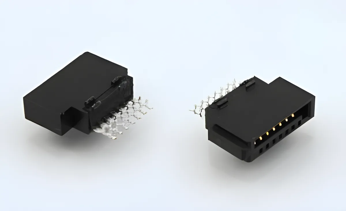
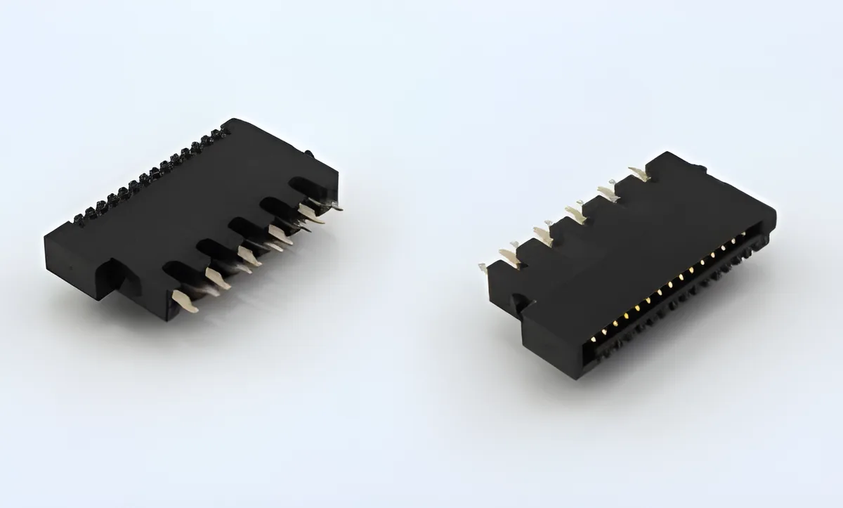
Figure 1. CZT SATA male-plug example identifies a physical construction for a continuity and vibration plan; no test result is depicted. CZT source · Original image.
Reproduce the installed support
Identify the board, drive or cable, enclosure guides and fasteners. Include the cable routing and local strain relief where relevant. These features determine the mechanical motion that reaches the interface.
Document the test fixture's attachment points. A rigid laboratory clamp may remove a motion present in the equipment, while a poorly designed fixture can add motion that the equipment never sees.
If mating cycles and vibration are both required, define the sequence and inspections between stages. Otherwise, later damage may be difficult to attribute to a particular condition.
Specify what interruption means
Define the circuits monitored, detection threshold and event-duration capability of the instrumentation. Choose criteria from the product requirements and applicable test documents. A result reported only as no open circuit lacks the information needed to understand what the equipment could detect.
| Record | Why it belongs in the report |
|---|---|
| Circuit map | Identifies the monitored paths |
| Detection settings | Defines sensitivity and duration coverage |
| Mounting arrangement | Reproduces the mechanical boundary |
| Operating condition | Distinguishes powered and unpowered trials |
| Time history | Associates events with test stages |
Verify the monitoring arrangement before testing the product. Intermittent fixture connections can create false failures, and an incorrectly mapped circuit can conceal a real interruption.
Examine post-test condition
Repeat the approved resistance measurements using the same path definition as the baseline. Inspect attachment features, mating alignment and the surrounding board or support structure. Record visible changes even if continuity is present.
For a hypothetical storage module, an event appearing only when a cable bends near its termination may require a separate cable investigation. Replacing the board receptacle first would remove evidence without isolating the cause.
Preserve suspect specimens and label every disconnection or teardown step. Remating can change an intermittent symptom, so the report should distinguish observations made before and after that intervention.
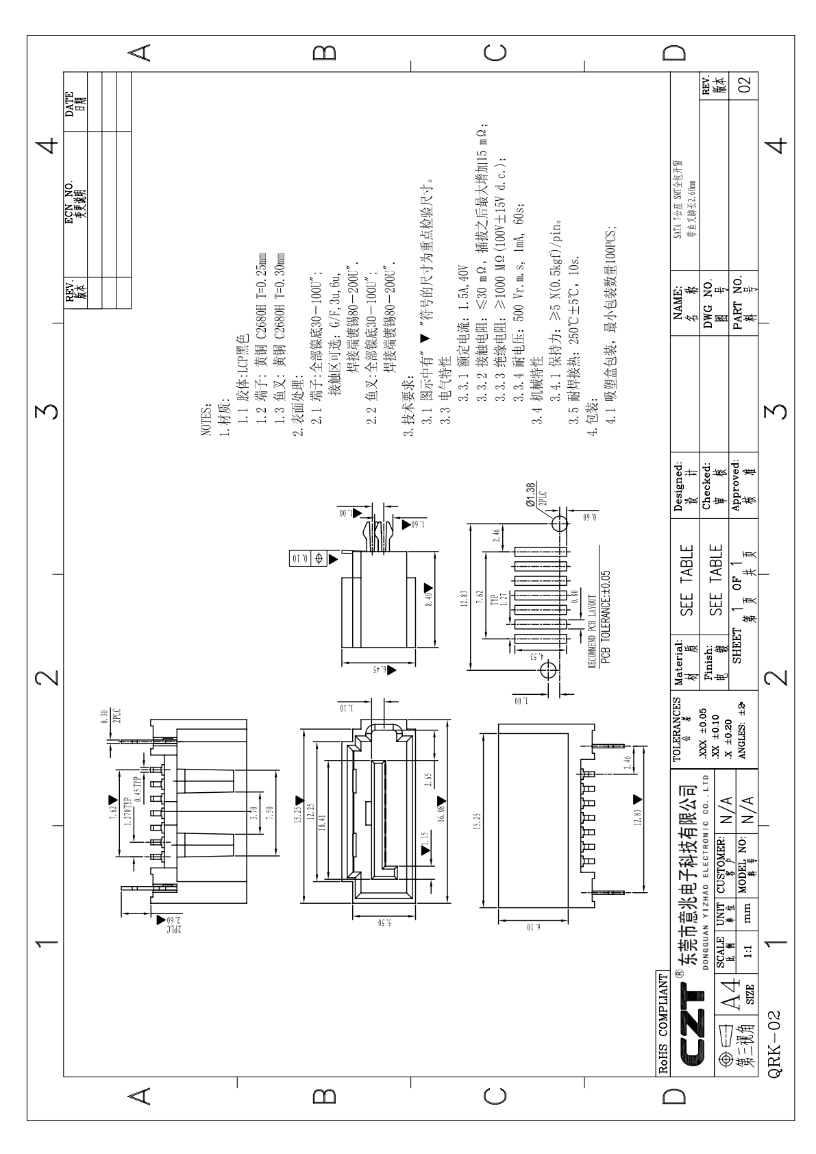
Figure 2. Official SATA drawing provides the sample and mounting reference for validation; include the actual mating assembly and installed supports. CZT source · Original PDF, page 1.
Connect findings to approval
Evaluate the complete set of mechanical, electrical and functional criteria. A surviving static connection does not override a detected in-test interruption. Equally, an instrumentation fault should be resolved before rejecting the product.
The final acceptance should name the connector or cable model, mating part, mounting configuration, test sequence and monitoring limits. That record gives engineering a defensible basis for deciding whether a later support, cable or connector change needs partial or full requalification.
Connect this review to CZT product information
Catalog references to discuss are listed below. Use the identifiers to request the current drawing and confirm the configuration required by your application.
| Catalog reference | Product information | Drawing record | Reference inquiry |
|---|---|---|---|
| SATA02 7PIN | SATA 7-pin catalog record, SATA02 | Listed PDF | Ask about this reference |
| SATA04 15PIN | SATA 15-pin catalog record, SATA04 | Listed PDF | Ask about this reference |
A catalog drawing reference is a starting document, not a substitute for reviewing its revision, options and suitability for the complete assembly.
Browse the relevant product family · View catalog resources
Discuss a drawing, sample or quotation
Share the part or family reference, current drawing revision, operating conditions and quantities. Include the specific checks described in this article so the inquiry identifies both the component and the evidence needed for your decision. Confirm sample availability and the proposed scope with the supplier.
Request a technical review or quotation
For broader context, read the related selection guide.