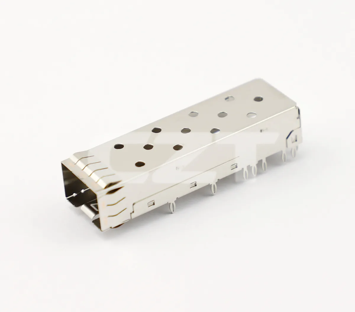
Intermittent behavior at an SFP port should be isolated across the module, receptacle, cage, PCB and optical path before assigning a connector failure. Start with a reproducible symptom and preserve the installed geometry. A link interruption can result from several mechanisms, and replacing a module once does not identify which one was present.

Figure 1. CZT SFP+ cage illustrates one mechanical part of an optical port; an intermittent-contact investigation must separately identify the electrical receptacle and PCB. CZT source · Original image.
Describe the interruption precisely
Record whether the symptom is link loss, module removal detection, management communication failure or traffic errors with the link still established. Capture host and module logs, software versions, temperature and any associated movement. These observations help choose the next test instead of treating every event as contact bounce.
Determine whether the symptom follows one module, one port or one operating condition. Use identified comparison samples and change one item at a time. Keep the cable and optical connection condition controlled during electrical-interface investigation.
Inspect the mechanical stack
Review module seating, latch engagement, cage position and receptacle alignment. Check whether the front panel or cable imposes force on the installed module. Inspect accessible mounting and solder joints using methods appropriate to the construction.
CZT's pluggable-I/O family lists separate cage and connector references. Use the exact installed identities in the investigation; a general SFP label cannot demonstrate the dimensional relationship of an unknown combination.
A controlled isolation matrix
| Change | What the observation may help distinguish |
|---|---|
| Known comparison module in suspect port | Port-related versus module-related behavior |
| Suspect module in comparison port | Whether the symptom follows the module |
| Controlled cable-route change | Sensitivity to external mechanical loading |
| Comparable thermal condition | Temperature-associated versus random occurrence |
| Board-level inspection or measurement | Receptacle and PCB interface concerns |
Each result is evidence, not a complete cause by itself. For example, a replacement module may fit differently enough to mask a marginal mechanical stack.
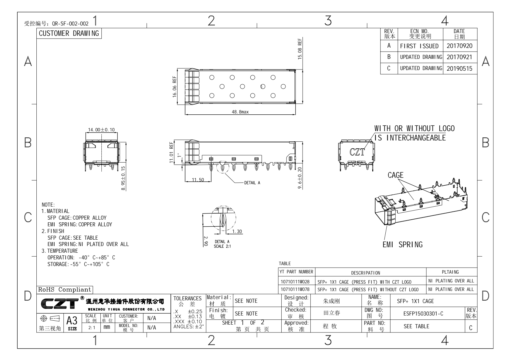
Figure 2. Official cage drawing helps document seating and mounting relationships before changing specimens during a port-interruption investigation. CZT source · Original PDF, page 1.
Examine contacts without erasing evidence
Document insertion marks, visible contamination and wear before cleaning or repeated mating. If disassembly or sectioning is planned, agree the sequence and retain both sides of the interface. Record how the failed sample was handled after removal.
Choose any contact-resistance or continuity measurement with a method suitable for the actual circuit and specimen. A convenient bench reading may not reproduce the operating load, position or temperature associated with the interruption.
Record the order of substitutions carefully. A symptom that disappears after several changes cannot confidently be assigned to the final replaced item unless earlier changes and their effects remain traceable.
The investigation report should connect the observed symptom to the supported mechanism, proposed correction and repeat test. If the evidence supports only a narrower finding, such as sensitivity to panel misalignment, state that boundary. Avoid translating it into an unsupported claim that every module or every receptacle of the same catalog family is defective. Retain the logs, installed photographs and comparison-sample identities so that the next reviewer can reproduce the reasoning.
Connect this review to CZT product information
Catalog references to discuss are listed below. Use the identifiers to request the current drawing and confirm the configuration required by your application.
| Catalog reference | Product information | Drawing record | Reference inquiry |
|---|---|---|---|
| 10710111W064 | SFP+ 1x1 receptacle catalog record, 10710111W064 | Listed PDF | Ask about this reference |
| 10710111W028 | SFP+ 1x1 cage, 10710111W028 | Listed PDF | Ask about this reference |
A catalog drawing reference is a starting document, not a substitute for reviewing its revision, options and suitability for the complete assembly.
Browse the relevant product family · View catalog resources
Discuss a drawing, sample or quotation
Share the part or family reference, current drawing revision, operating conditions and quantities. Include the specific checks described in this article so the inquiry identifies both the component and the evidence needed for your decision. Confirm sample availability and the proposed scope with the supplier.
Request a technical review or quotation
For broader context, read the related selection guide.