Grounding and shield termination for an industrial harness should be defined by the equipment's electrical and EMC design. A generic instruction to connect the shield at one end or both ends can conflict with the actual system requirements. The harness drawing must implement the approved strategy, including the physical termination details.
Siemens addresses cable shielding within its equipment-specific EMC configuration manual. Use such manufacturer guidance within its stated scope. Candidates in the wire-harness family still require application-specific definition and system verification.
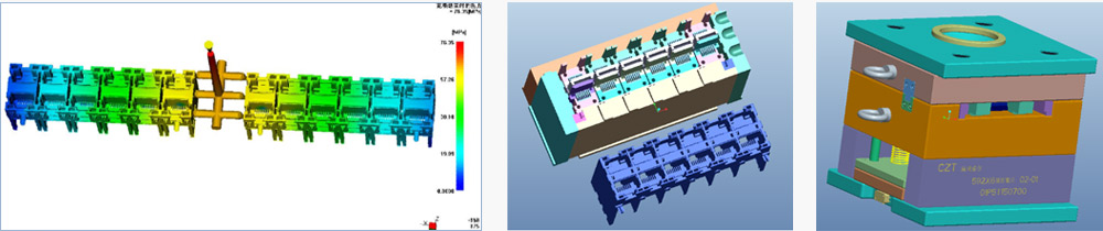
Figure 1. CZT tooling CAD example, shown as engineering-process context; it does not depict an approved shield or ground path. CZT source · Original image.
Separate the electrical functions
Identify protective bonding, chassis connection, signal return and cable shielding using the project's approved terminology. Do not label every conductor ground and assume the manufacturing team can infer the intended relationships.
Create a diagram showing where each shield starts, ends and connects to the equipment. Identify any intentional isolation and the components that provide it. Keep this diagram consistent with the circuit and enclosure design.
The responsible system engineer should resolve the strategy before the supplier turns it into a manufacturing drawing. Harness assembly alone cannot decide the equipment's grounding architecture.
Define the physical termination
Specify the shield preparation, exposed length, termination hardware and connection location. Record whether the shield connects through a connector shell, clamp, drain-wire arrangement or another approved structure.
| Drawing detail | Why it is needed |
|---|---|
| Shield endpoint | Removes uncertainty about where shielding stops |
| Connection structure | Defines the actual conductive interface |
| Preparation length | Makes the assembly reproducible |
| Insulation and protection | Controls unintended contact and damage |
| Verification points | Connects the drawing to inspection |
Avoid replacing one structure with another as a workshop convenience. Two arrangements can show DC continuity while having different system behavior. Treat a physical change as an engineering review item.
Plan inspection and system checks
Define the continuity and isolation checks that can be performed on the harness itself. Keep them separate from the equipment-level EMC evaluation. A harness passing its connection map does not demonstrate that the complete machine meets an EMC requirement.
For a hypothetical encoder harness, the drawing may control a shield clamp at the cabinet entry and a specific connector-shell termination near the sensor. If either location changes, inspect the assembly and reassess the relevant system evidence rather than accepting the same DC result as a complete substitute.
Photograph the first approved preparation and termination so inspectors can compare later production with an actual controlled reference.

Figure 2. CZT harness-production equipment, shown as process context. The image does not establish a particular shield termination or equipment EMC result. CZT source · Original image.
Keep responsibilities visible
State which components the harness supplier provides and which connections are completed during equipment installation. Include the required surface preparation and fastening references where the equipment assembly controls them.
Release the diagram, preparation details and verification boundary together. This gives procurement a specific assembly requirement and gives system engineering a traceable configuration for testing. It also prevents a broad shielded-cable description from becoming an unsupported claim about the EMC performance of the finished equipment.
Connect this review to CZT product information
Start with the relevant CZT product family and provide the original interface reference or controlled drawing. Ask which configurations and supporting documents are available for the task described here. Confirm the mating arrangement, required features and project conditions before choosing an orderable part.
Browse the relevant product family · View catalog resources
Discuss a drawing, sample or quotation
Share the part or family reference, current drawing revision, operating conditions and quantities. Include the specific checks described in this article so the inquiry identifies both the component and the evidence needed for your decision. Confirm sample availability and the proposed scope with the supplier.
Request a technical review or quotation
For broader context, read the related selection guide.