Moving from two-pair to four-pair PoE requires review of every intended power path through the RJ45 magnetic interface. The enclosure, eight-contact mating face and data-link function can remain familiar while the center-tap connections and thermal workload change.
Use the internal circuit of the candidate in the CZT integrated magnetics range as the working reference. The correct question is which paths the selected module supports in the proposed system, rather than whether its product description mentions PoE.
Map the powered pairsets
Draw each cable pair and its associated magnetic circuit. Identify where power is injected or extracted and how the PoE controller connects to those nodes. Keep the PHY-side bias network separate from the cable-side power network.
Then compare the proposed operating configuration with the module documentation. Confirm which center taps are accessible and whether any are internally connected. This is especially important when an existing PCB is being reused: a compatible footprint does not prove the power network is unchanged.
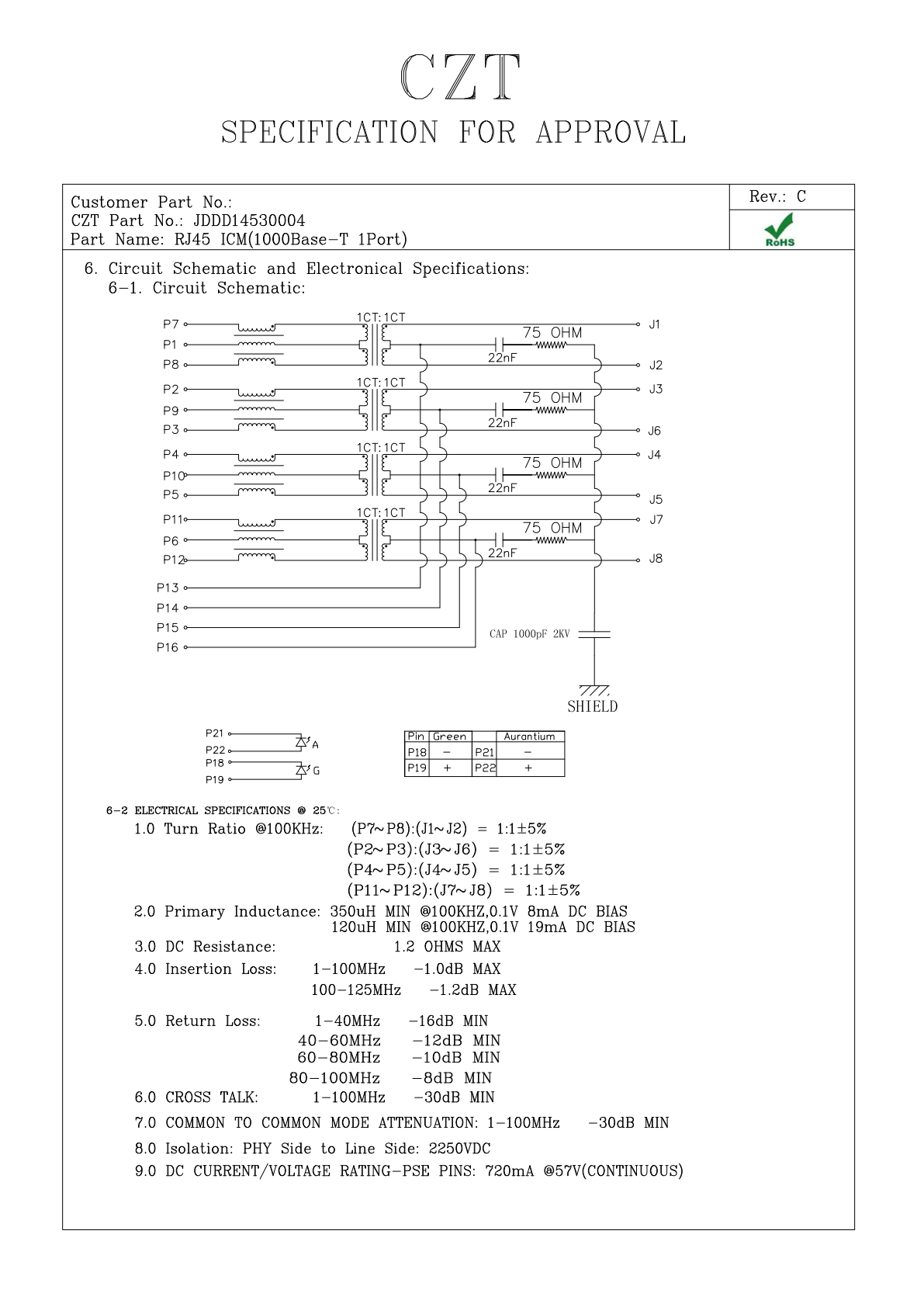
Figure 1. JDDD14530004: internal circuit and electrical specification fields from the official manufacturer specification, PDF page 6. CZT source · Original PDF, page 6.
Compare architectures with explicit fields
| Question | Two-pair implementation | Four-pair implementation |
|---|---|---|
| Active power paths | Identify selected pairset | Identify both pairsets |
| Accessible nodes | Record required center taps | Record all required center taps |
| Loading assumptions | Document actual current distribution | Document distribution and imbalance cases |
| Controller interface | Map to approved circuit | Map each additional connection |
| Thermal review | Evaluate used paths | Evaluate simultaneous path loading |
The table is a design worksheet, not a universal wiring diagram. Actual connections follow the selected controller and PHY documentation.
Review current distribution, not just total power
A port's total power target is useful at the system level, but a connector is stressed through individual contacts and winding paths. Review the relevant current limits, resistance characteristics and balance requirements using the actual operating mode.
Where current can divide between parallel paths, do not assume ideal equality without an applicable basis. Define the imbalance cases that the project needs to evaluate and include them in component and board qualification.
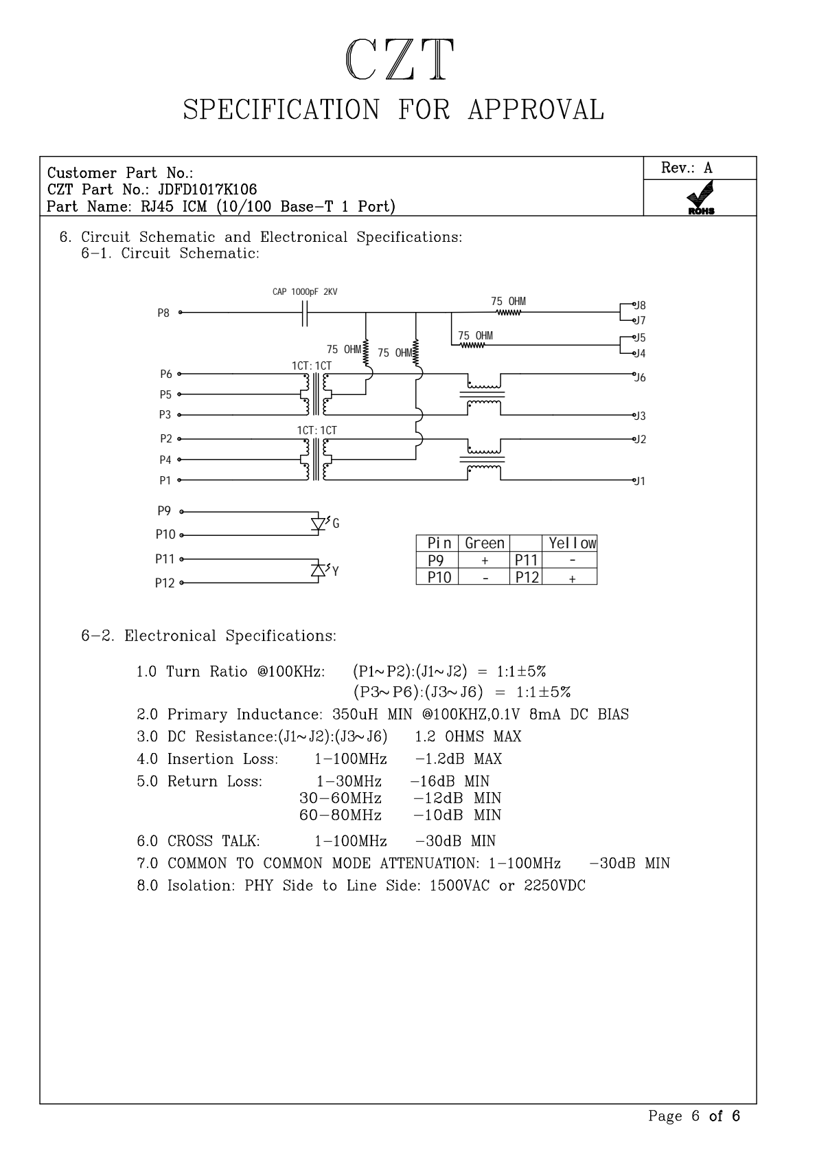
Figure 2. JDFD1017K106: internal circuit and electrical specification fields from the official manufacturer specification, PDF page 6. CZT source · Original PDF, page 6.
Plan a controlled migration test
For a hypothetical switch redesign, first confirm the schematic changes, then verify pair mapping on unpowered samples. After electrical review, exercise the intended power modes with representative cables and link partners. Monitor link behavior and temperature under the planned load combinations.
If the design changes both the PoE controller and ICM, retain enough intermediate evidence to distinguish a controller-configuration issue from a connector-interface issue. This makes troubleshooting faster than treating the complete port as one unexplained failure.
Specify the purchasing outcome
The approved record should identify the exact ICM circuit, operating configuration, drawings and test evidence. Purchasing can then request the reviewed variant. A shortened requirement such as “four-pair PoE jack” should be supported by that technical package, because it does not describe all of the interface decisions on its own.
Connect this review to CZT product information
Start with the relevant CZT product family and provide the original interface reference or controlled drawing. Ask which configurations and supporting documents are available for the task described here. Confirm the mating arrangement, required features and project conditions before choosing an orderable part.
Browse the relevant product family · View catalog resources
Discuss a drawing, sample or quotation
Share the part or family reference, current drawing revision, operating conditions and quantities. Include the specific checks described in this article so the inquiry identifies both the component and the evidence needed for your decision. Confirm sample availability and the proposed scope with the supplier.
Request a technical review or quotation
For broader context, read the related selection guide.