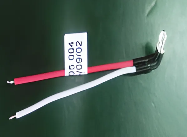
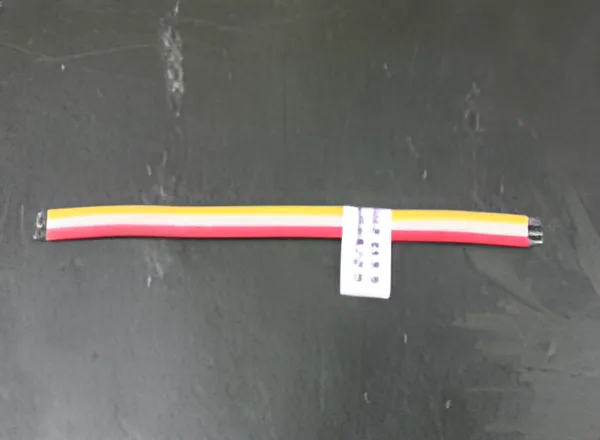
A build-board fit does not establish that a harness fits the equipment. The board controls manufacturing geometry, while the machine introduces brackets, moving parts, covers and service access. Routing acceptance should connect both environments through documented installation checks.
For an assembly developed from the wire-harness family, use a controlled harness drawing and the corresponding equipment revision. Record the actual connector, support and protective components fitted to the sample so the installation result remains traceable.
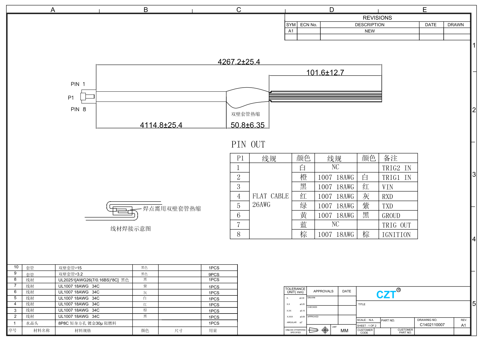
Figure 1. Official cable drawing. Defined lengths and endpoint geometry support the routing review; this record does not demonstrate fit in the hypothetical equipment. CZT source · Original PDF, page 1.
Define the installed route
Mark connector locations, clips, ties, brackets and pass-throughs on the equipment model. Identify the intended route rather than allowing the installer to choose any available path that happens to reach.
Add moving-component envelopes and cover-closing paths. Check the equipment in all required positions, including service access where appropriate. A harness that fits with the cover removed may be compressed or displaced when the equipment is completed.
Distinguish functional slack from uncontrolled excess length. Each loop should have a purpose and a defined location rather than being tucked behind a bracket after installation.
Check the connector exit and supports
Inspect the wire exit angle, local strain relief and distance to the first support using the relevant cable and connector requirements. Confirm that the route does not create continuous tension at the mating interface.
| Installation area | Acceptance observation |
|---|---|
| Connector end | Full seating, release access and no unintended pull |
| Fixed supports | Correct location and controlled restraint |
| Pass-through | Approved edge protection and clearance |
| Moving region | Route stays within the evaluated motion envelope |
| Covers and panels | No pinching or forced repositioning |
Where the design uses moving cable, obtain application-specific routing and bend requirements. General harness practices do not establish a cable's dynamic capability.
Record deviations where they occur
Use annotated photographs showing the installed route and the affected reference points. Record whether an issue comes from harness dimensions, equipment geometry or an unclear instruction.
For a hypothetical inspection machine, the harness may fit its build board perfectly but rub a cover rib during motion. Moving a clip, changing the protective treatment or revising the cover are different remedies. Choose one through engineering review rather than instructing the operator to route around the problem differently each time.
After a change, repeat the affected installed checks. Preserve the original finding so the reason for the new dimension or support location remains understandable.

Figure 2. CZT harness-production area. The official production-area photograph supports the build-board-to-installation handoff discussion, without claiming a completed installation trial. CZT source · Original image.
Approve a reproducible installation
Release the harness drawing together with the route, support details and necessary assembly instructions. Identify the approved equipment revision and unresolved installation states, if any.
When the enclosure, bracket or mating connector position changes, compare it with the installation record. This keeps a previously accepted harness from being assumed suitable for a new mechanical arrangement. The result should be a route that production and service can reproduce, not merely one successful trial assembled by the engineer who designed it.
Connect this review to CZT product information
Catalog references to discuss are listed below. Use the identifiers to request the current drawing and confirm the configuration required by your application.
| Catalog reference | Product information | Drawing record | Reference inquiry |
|---|---|---|---|
| LED CABLE | LED cable catalog record | Listed PDF | Ask about this reference |
| 3C CABLE | 3C electronic cable catalog record | Listed PDF | Ask about this reference |
A catalog drawing reference is a starting document, not a substitute for reviewing its revision, options and suitability for the complete assembly.
Browse the relevant product family · View catalog resources
Discuss a drawing, sample or quotation
Share the part or family reference, current drawing revision, operating conditions and quantities. Include the specific checks described in this article so the inquiry identifies both the component and the evidence needed for your decision. Confirm sample availability and the proposed scope with the supplier.
Request a technical review or quotation
For broader context, read the related selection guide.