HDMI shell-anchor validation should reproduce the cable loads transmitted into the PCB and enclosure. A receptacle may withstand ordinary straight mating yet experience a different stress when a stiff cable bends close to the panel. The qualification question is how the installed assembly handles that force path.
Use the exact drawing for a candidate from the USB and HDMI family. Shell attachments, locating features and board standoff must be checked individually; the mating interface alone does not define the mechanical retention arrangement.

Figure 1. CZT HDMI receptacle example illustrates the shell and board attachment that transmit external cable loads into the assembly. CZT source · Original image.
Define the cable geometry and load directions
Record the cable construction, overmold dimensions and distance from the connector to the point where the load is applied. This distance affects the mechanical moment at the port. Include the intended cable routing and any external clamps.
Separate upward, downward and sideways conditions when those directions are credible in the application. A rack-mounted product may have cable weight continuously pulling in one direction while a service operation creates a brief force in another.
Select loads and acceptance limits from the equipment requirements and relevant component documentation. Do not turn an uncontrolled hand bend into a published retention rating.
Inspect the structural path
Map the shell anchors, local board area, nearby fasteners and enclosure contact points. Determine whether the intended loads reach strong support areas or cause the PCB to flex between distant mounts.
| Observation | What it helps distinguish |
|---|---|
| Shell motion relative to board | Attachment or joint movement |
| Board motion relative to enclosure | Support stiffness and location |
| Plug movement inside receptacle | Mating-interface behavior |
| Panel contact during loading | Unintended enclosure load transfer |
An opening that presses against the plug may make the board appear better supported while creating another stress concentration. Treat that contact as part of the design rather than an incidental aid during testing.
Check electrical and mechanical changes together
Take baseline photographs and relevant electrical measurements. Apply the agreed load sequence while monitoring the paths and functions defined in the plan. Afterwards, inspect joints, shell position and board condition, then repeat the same measurements.
A hypothetical display controller might continue showing an image despite a visibly cracked shell joint. That result should not be recorded as a complete pass merely because communication survived the trial. Mechanical acceptance remains a separate requirement.
Preserve failed parts before rework. Photographs after replacing the receptacle cannot establish the original crack location or sequence.
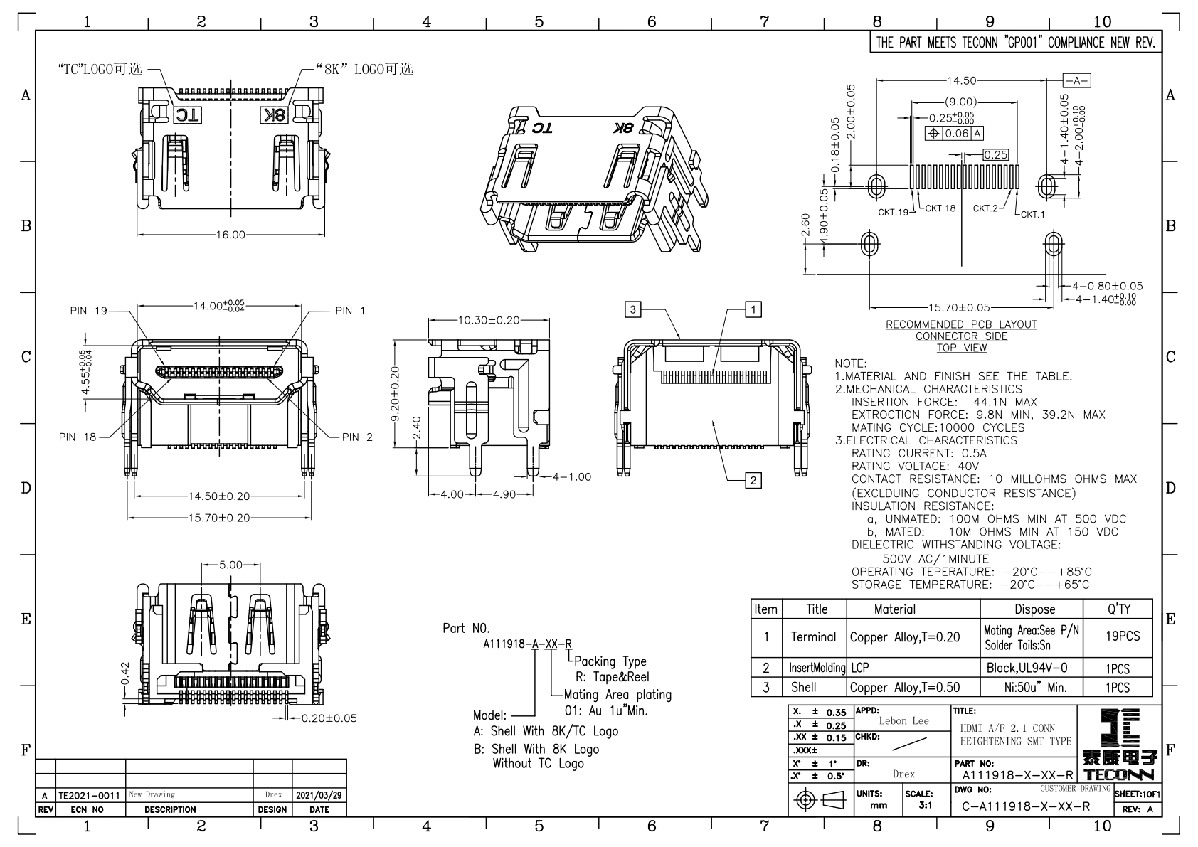
Figure 2. Official HDMI drawing supports a defined retention-test specimen; cable moment, board support and acceptance criteria require their own plan. CZT source · Original PDF, page 1.
Use the result to approve the assembly
If a support change is proposed, keep the connector and cable conditions constant while comparing it. This makes the comparison useful for identifying whether the new support addresses the observed mechanism.
Retain the sample IDs, drawing revisions, load setup, monitoring method and post-test inspection. State the conditions covered by approval and those still open. When the product later changes its cable recommendation or panel geometry, the recorded load path shows which aspects of the validation need review.
Connect this review to CZT product information
Start with the relevant CZT product family and provide the original interface reference or controlled drawing. Ask which configurations and supporting documents are available for the task described here. Confirm the mating arrangement, required features and project conditions before choosing an orderable part.
Browse the relevant product family · View catalog resources
Discuss a drawing, sample or quotation
Share the part or family reference, current drawing revision, operating conditions and quantities. Include the specific checks described in this article so the inquiry identifies both the component and the evidence needed for your decision. Confirm sample availability and the proposed scope with the supplier.
Request a technical review or quotation
For broader context, read the related selection guide.