Validate PV connector cable retention and side loading as different mechanical conditions. An axial pull test addresses a particular load direction; it does not automatically describe what happens when a cable bends at the seal or pushes the connector sideways in the installation.
For an identified candidate in the CZT PV connector family, use the approved cable and assembly instructions. The test should evaluate the intended construction and routing rather than an improvised fixture arrangement.
Draw the installed support pattern
Identify the connector position, cable exit direction, support points and expected movement. Show which section of cable remains free and where an external load can enter the connection.
Review the cable manufacturer's bend guidance and the connector's routing instructions. Do not use a retention test to justify an installation geometry that the component instructions prohibit.

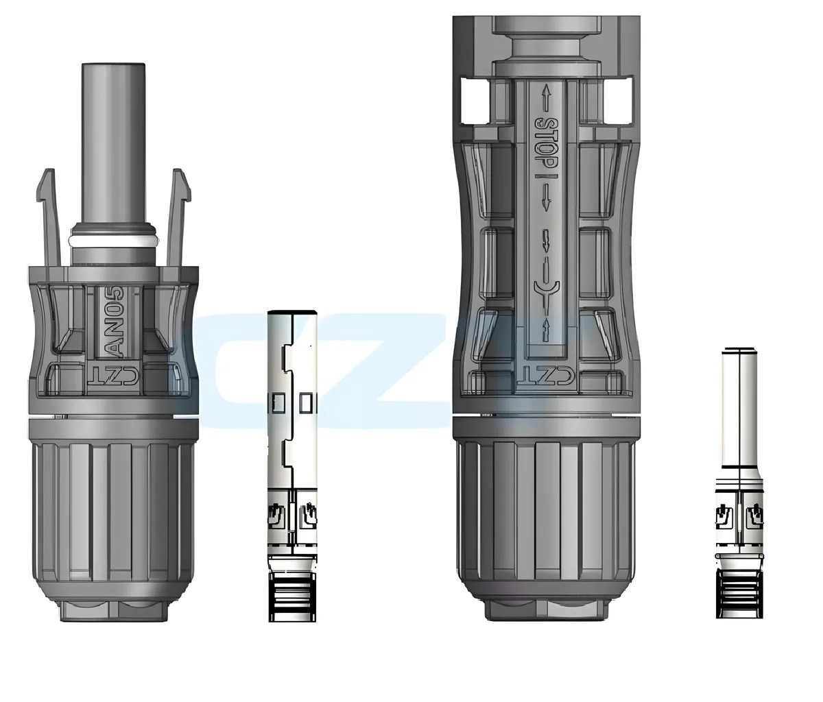
Figure 1. AN05 cable-end connector bodies and separate contact components in CZT's official product illustration. CZT source · Original image.
Separate the mechanical cases
Define axial loading, side loading, bending and any other project-relevant movement individually. Each case needs a stated attachment point, direction and fixture boundary. A test name without that geometry can mean different things to different laboratories.
Identify whether the connector is mated, panel-mounted or held in another specified condition. The fixture should not provide support that is absent from the intended product unless that difference is explicitly part of a diagnostic test.
Use a mechanical validation sheet
| Test element | Required definition |
|---|---|
| Assembly | Connector, contact, seal and cable identities |
| Mounting | Mating or panel condition and support locations |
| Load | Direction, application point and approved profile |
| Cable geometry | Exit condition and bend arrangement |
| Observations | Movement, visible damage and retention behavior |
| Follow-up | Required electrical and sealing checks |
Set the acceptance reference before testing. Avoid borrowing a force value from another connector system or treating absence of visible damage as the only requirement.

Figure 2. Tensile-test equipment photographed in CZT's official technical-development gallery. CZT source · Original image.
Inspect the consequences of loading
After the defined mechanical exposure, inspect cable position, housing condition and the relevant interface features. Where required, repeat electrical or sealing evaluations using the approved method.
A hypothetical sample could retain the cable under an axial check yet show an unresolved sealing change after side loading. The two results are not contradictory; they concern different conditions and functions. Record both rather than compressing them into one retention verdict.
Connect the result to installation control
If a problem appears only under a particular routing arrangement, investigate the support geometry as well as the component. A better cable-support location may address the actual load path more directly than an arbitrary increase in assembly tightness.
Preserve the validated cable, seal, assembly method and routing boundary together. Changes in cable stiffness, support spacing or installation orientation can alter the mechanical condition even when the connector model remains the same. That record gives engineering and purchasing a practical basis for reviewing those changes without overstating what a single pull test established.
Connect this review to CZT product information
Catalog references to discuss are listed below. Use the identifiers to request the current drawing and confirm the configuration required by your application.
| Catalog reference | Product information | Drawing record | Reference inquiry |
|---|---|---|---|
| PV cable-end connector, AN05 | PV cable-end connector, AN05 | Request the current drawing | Ask about this reference |
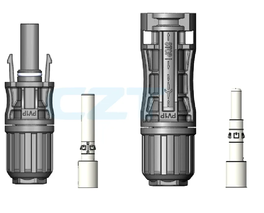
| PV cable-end connector, PV1P-A | PV cable-end connector, PV1P-A | Request the current drawing | Ask about this reference |
These entries identify catalog families. Their listing does not establish a numerical rating, finished-part tolerance or test approval; obtain that evidence for the requested revision.
Browse the relevant product family · View catalog resources
Discuss a drawing, sample or quotation
Share the part or family reference, current drawing revision, operating conditions and quantities. Include the specific checks described in this article so the inquiry identifies both the component and the evidence needed for your decision. Confirm sample availability and the proposed scope with the supplier.
Request a technical review or quotation
For broader context, read the related selection guide.