A panel-mounted PV connector seals reliably only when its connector geometry, sealing element, mounting hardware and enclosure panel are reviewed as one assembly. A connector-level protection claim cannot settle whether a particular combiner-box cutout will seal. The practical starting point is a controlled cross-section showing every surface that locates or compresses the seal.
Establish the panel interface
Set the mating-face position relative to an enclosure datum. Then identify the panel thickness range, cutout profile, anti-rotation feature and usable flat sealing land. Paint, burrs, embossing and panel distortion belong in this review because the sealing element contacts the finished enclosure, not an ideal CAD surface.
CZT lists panel-side products in its solar PV connector family. AN06 and PV1P-B are catalog examples to investigate. Their names alone do not establish a mounting-hole size, tightening torque or sealing arrangement. Request the specific drawing and installation instructions before assigning either to a design.
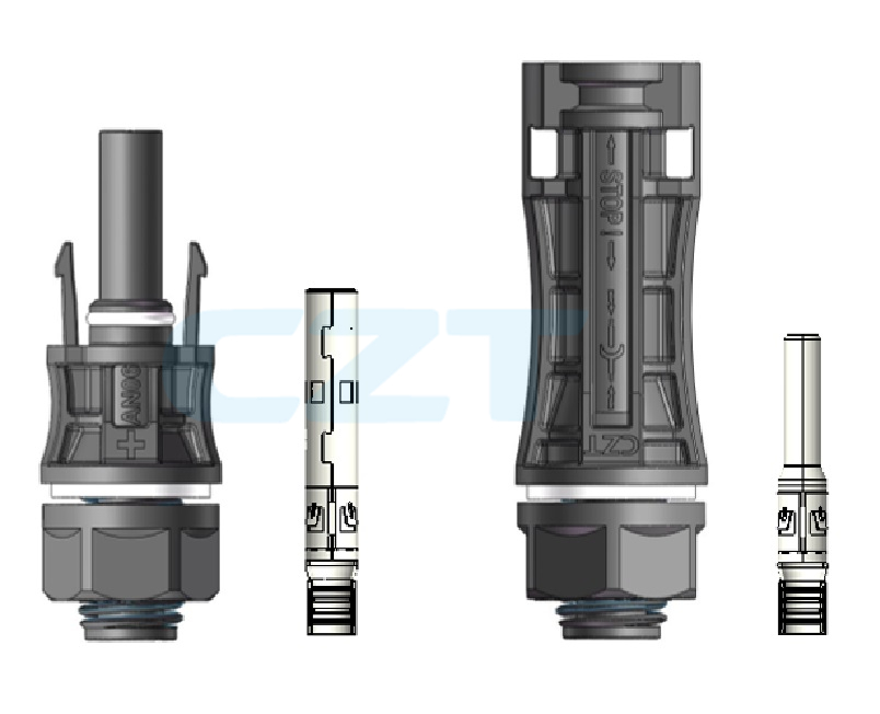
Figure 1. AN06 board-end PV connector components. Family-interface context only; panel-mount sealing is not established by the illustration. CZT source · Original image.
Make compression a controlled result
The nut position is not a complete definition of seal compression. The assembled stack includes the panel, washers, seal, shoulders and any coating under the seating surfaces. Ask which feature provides the mechanical stop and which tolerances change the final compression. Include the permitted orientation and hardware order on the assembly drawing.
Do not solve an uncertain interface by adding sealant without review. An added material may change friction, serviceability or the intended seal geometry. Its compatibility and assembly process would need their own evidence.
Use a drawing review table
| Drawing field | Question to resolve before release |
|---|---|
| Panel and coating | What finished thickness and flatness range applies? |
| Cutout and datum | How are position, rotation and edge quality controlled? |
| Seal and hardware | Which exact parts, orientation and assembly sequence apply? |
| Tightening method | What tool, torque and anti-rotation method are specified? |
| Rear clearance | Can cables be routed without loading the mounted body? |
Treat unanswered rows as open design actions. A successful fit of one hand-built sample does not establish tolerance coverage.
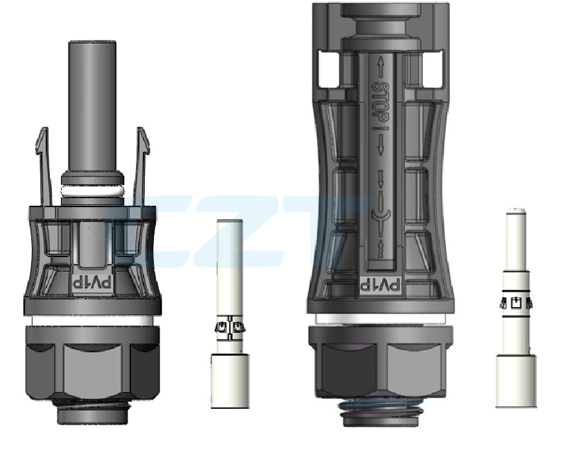
Figure 2. PV1P-B board-end PV connector components. The illustration does not establish a combiner-box mounting or sealing configuration. CZT source · Original image.
Validate the assembled enclosure
Build samples representing the relevant panel and component limits. Inspect seating and rotational security before checking environmental protection. Record the complete connector pair, cable, cap if used, panel revision and tightening method with every result. State whether the test concerns a mated or unmated condition.
For example, if a thicker coating reduces available thread engagement, the corrective decision may concern the panel process rather than the connector. A nominal-thickness test would miss that interaction. Repeat the assessment after a changed coating or gasket, even if the connector part number remains unchanged.
Stäubli's panel-receptacle instructions illustrate the importance of product-specific assembly instructions. Their dimensions and rules apply to the stated Stäubli products; they are not installation specifications for CZT parts. Release the enclosure interface only after the selected assembly has documented installation and verification conditions.
Connect this review to CZT product information
Start with the relevant CZT product family and provide the original interface reference or controlled drawing. Ask which configurations and supporting documents are available for the task described here. Confirm the mating arrangement, required features and project conditions before choosing an orderable part.
Browse the relevant product family · View catalog resources
Discuss a drawing, sample or quotation
Share the part or family reference, current drawing revision, operating conditions and quantities. Include the specific checks described in this article so the inquiry identifies both the component and the evidence needed for your decision. Confirm sample availability and the proposed scope with the supplier.
Request a technical review or quotation
For broader context, read the related selection guide.