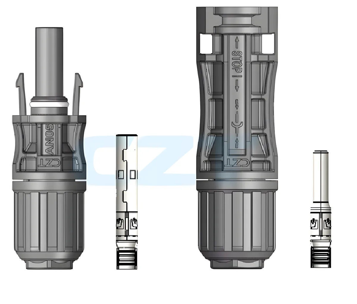
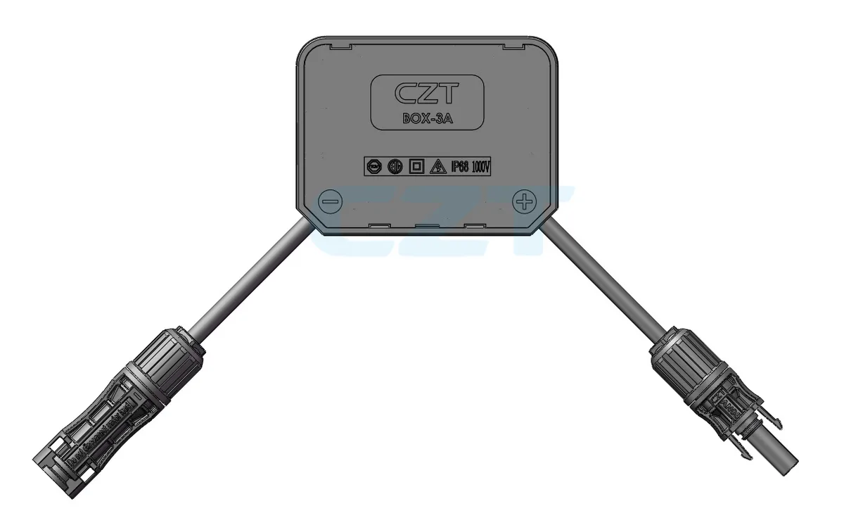
If you work with solar photovoltaic systems, you have almost certainly handled an MC4 connector. These small but critical components form the electrical backbone of nearly every modern solar installation, from residential rooftops to utility-scale solar farms.
MC4 connectors are the global standard for connecting solar panels, inverters, and balance-of-system components. Their tool-free snap-lock design, weatherproof housing, and touch-safe contacts make them the safest and most reliable way to wire a PV array. In this guide, we cover everything you need to know: specifications, types, installation procedures, and the best practices that separate a professional installation from a potential fire hazard.
Many buyers also land here with a more specific question: what is the difference between 30A, 45A, and 60A MC4 connectors, and are they interchangeable? Whether you are a solar installer, system designer, or procurement engineer sourcing solar panel connectors for your next project, this article will give you the technical depth you need.

MC4 Connector 30A vs 45A vs 60A: Quick Answer
The short answer is that 30A, 45A, and 60A MC4-compatible connectors are not just different labels on the same part. The current rating depends on the complete contact system: contact geometry, spring force, conductor size, crimp quality, thermal rise performance, and the certification test conditions behind the datasheet.
| Rating class | Typical use case | What to verify before selecting |
|---|---|---|
| 30A | Standard residential and commercial PV strings | IEC 62852 / UL compliance, cable size, matched mating pair |
| 45A | Higher-current modules, harnesses, or branch assemblies | Approved conductor range, temperature rise data, same-brand mating |
| 60A | Specialized high-current PV or energy-storage assemblies | Manufacturer-specific certification, connector body design, heat-rise margin |
In practice, a 30A MC4 connector is enough for most mainstream PV strings. 45A and 60A products exist, but they are usually manufacturer-specific high-current variants and should not be treated as automatically interchangeable with a standard 30A pair. If your design depends on higher current, confirm the exact part number, matching cable cross-section, and certified test report rather than assuming all MC4-compatible housings perform the same.
What Is an MC4 Connector?
The MC4 connector is a single-contact electrical connector designed specifically for photovoltaic systems. The name stands for Multi-Contact 4 mm, referring to the 4 mm diameter contact pin at its core. It was originally developed by Multi-Contact (now Staubli Electrical Connectors), a Swiss company with decades of experience in high-reliability electrical connections.
First introduced in the early 2000s, the MC4 design quickly replaced older MC3 connectors and competing formats. The key innovation was a locking mechanism that prevents accidental disconnection while still allowing tool-free mating. Unlike its predecessor, the MC4 also features touch-safe contacts, meaning the live electrical parts are fully recessed inside the housing. You cannot accidentally touch a live conductor.
Today, the MC4 form factor is referenced in the international standard IEC 62852 (Connectors for DC application in photovoltaic systems). While Staubli holds the original trademark, dozens of manufacturers worldwide produce MC4-compatible connectors. The design has become so ubiquitous that "MC4" is often used generically to describe any solar PV connector with this form factor.
The MC4 connector's dominance comes down to three things: safety, reliability, and ease of installation. A properly assembled MC4 connection is IP68-rated, meaning it is completely dust-tight and can withstand continuous submersion. It handles the high DC voltages and currents found in modern solar arrays. And it can be mated in seconds without any special tools.
MC4 Connector Amp Ratings, Voltage and Cable Specifications
Understanding the technical specifications of MC4 connectors is essential for proper system design and component selection. Below is a comprehensive specification table covering the most common MC4 and MC4-EVO2 variants.
| Parameter | MC4 (Standard) | MC4-EVO2 (High Current) |
|---|---|---|
| Rated Voltage | 1000V DC | 1500V DC |
| Rated Current | 30A | 40A (up to 70A) |
| Contact Resistance | < 0.5 mOhm | < 0.5 mOhm |
| Insulation Resistance | > 500 MOhm | > 500 MOhm |
| IP Rating | IP65 / IP68 (mated) | IP68 (mated) |
| Temperature Range | -40C to +85C | -40C to +85C |
| Wire Gauge (AWG) | 14 AWG to 10 AWG | 14 AWG to 8 AWG |
| Wire Gauge (mm2) | 2.5 to 6.0 mm2 | 2.5 to 10.0 mm2 |
| Contact Material | Tin-plated copper | Silver-plated copper |
| Housing Material | PPO (Polyphenylene Oxide) | PPO |
| UV Resistance | Yes (UL 746C f1) | Yes (UL 746C f1) |
| Mating Cycles | > 100 | > 100 |
| Certifications | TUV, UL | TUV, UL |
A few key points to note from these specs:
Voltage ratings have evolved with the industry. Older MC4 connectors were rated for 600V or 1000V DC systems. As solar installations moved toward 1500V string architectures to reduce wiring costs, the MC4-EVO2 was introduced to handle the higher voltage class. Always verify that your connectors match your system voltage.
Current ratings are equally important. A standard 30A MC4 connector is sufficient for most residential and commercial panels, which typically produce 10-15A at maximum power. However, high-current modules and parallel string configurations may require 40A or higher-rated connectors.
The IP68 rating only applies when the connector pair is properly mated. An unmated connector left exposed to the elements will allow water ingress. Always cap unused connectors with appropriate dust covers.
Temperature range of -40C to +85C covers virtually all terrestrial solar installations. However, the contact temperature during operation depends heavily on crimp quality. A poor crimp increases contact resistance, which generates heat, which further degrades the connection in a dangerous feedback loop.
Looking for MC4 connectors? CZT manufactures 30A, 45A, and 60A MC4-compatible connectors — TUV certified, IEC 62852 compliant, and available from MOQ 100 pcs. Browse MC4 connectors → or request a quote.
MC4 Connector Types and Compatibility Options
The MC4 ecosystem extends well beyond the basic male-female pair. Here is a breakdown of the most common MC4 connector types you will encounter in solar installations.
Male and Female Inline Connectors
The standard MC4 pair consists of a male connector (with a protruding pin contact) and a female connector (with a socket contact). These are used for the vast majority of panel-to-panel and panel-to-inverter connections. They snap together with an audible click and require a disconnect tool (or two flat-blade tools) to separate.
Branch Connectors (Y-Type and T-Type)
Branch connectors allow you to combine two or more parallel strings into a single output. A Y-branch connector splits one input into two outputs (or combines two inputs into one). A T-branch connector provides a similar function in a different physical configuration. These are commonly used at string combiners and in systems where multiple panels feed into a single input.
Panel-Mount Connectors
Panel-mount MC4 connectors are designed to be permanently installed on junction boxes or enclosures. They feature a flange or threaded mounting mechanism that provides a weatherproof feedthrough. These are standard on the back of virtually every solar panel manufactured today.
Inline Fuse Connectors
These specialized MC4 connectors incorporate an inline fuse holder, typically for 10A to 30A fuses. They provide overcurrent protection at the string level without requiring a separate fuse box. They are particularly useful in systems with three or more parallel strings where NEC 690.9 requires string-level fusing.
Extension Cables
Pre-assembled MC4 extension cables come in standard lengths (typically 1m to 10m) with connectors already crimped and tested at the factory. They save installation time and eliminate the risk of field crimping errors. For renewable energy projects with long cable runs, factory-assembled cables are strongly recommended.
MC4 Connector Types Comparison
| Type | Typical Use | Contacts | Notes |
|---|---|---|---|
| Male/Female Pair | Panel-to-panel, panel-to-inverter | 1+1 | Most common type |
| Y-Branch (2-to-1) | Parallel string combining | 2+1 or 1+2 | Available in M-F-F and F-M-M |
| T-Branch | Parallel string combining | 2+1 | Lower profile than Y-branch |
| 3-to-1 Branch | Three-string combining | 3+1 | Less common, check current rating |
| Panel Mount | Junction boxes, enclosures | 1 | Flange or threaded mount |
| Inline Fuse | String-level overcurrent protection | 1+1 | Accepts standard PV fuses |
| Extension Cable | Long cable runs | 1+1 (pre-assembled) | Factory-tested, various lengths |
| Dust Cap | Protecting unmated connectors | 0 | Essential for unused connectors |
MC4 vs MC4-Compatible Connectors
This is one of the most important and most misunderstood topics in solar installation. There is a critical difference between genuine MC4 connectors manufactured by Staubli and MC4-compatible connectors produced by other manufacturers.
The Cross-Compatibility Problem
While MC4-compatible connectors from different manufacturers may look identical and physically mate with each other, mixing brands is not recommended and may void warranties and certifications. Here is why:
The MC4 form factor is not an open standard with tight dimensional tolerances shared across manufacturers. Each manufacturer designs their own contact geometry, sealing system, and locking mechanism to be compatible with their own products. When you mate a connector from Brand A with a connector from Brand B, you may get:
- Slightly different contact pressure, leading to higher resistance
- Imperfect O-ring sealing, compromising the IP68 rating
- Locking mechanisms that do not fully engage
- Accelerated wear on contacts due to dimensional mismatch
Safety and Certification Implications
TUV and UL certifications for MC4 connectors are granted for matched pairs from the same manufacturer. When you cross-mate connectors from different brands, the certification is technically void. This matters for insurance, code compliance, and long-term reliability.
Multiple industry studies have linked cross-mated connectors to higher rates of:
- Contact overheating and hot spots
- Arc faults
- Ground faults from water ingress
- Connector failures requiring costly truck rolls
The Industry Response
The solar industry has taken this issue seriously. The MC4 Connector Compatibility Standard (IEC TS 62852) now includes specific testing requirements for connectors that claim cross-compatibility. TUV Rheinland offers a specific cross-compatibility certification program.
When sourcing connectors, always verify that your supplier provides matched male-female pairs from the same production line. At CZT, all our solar PV connectors are sold as certified matched pairs and tested as complete assemblies.
What to Look For
When evaluating MC4-compatible connectors, check for:
- TUV 2PfG 1908 certification (the specific standard for PV connectors)
- UL 6703 listing
- Contact resistance test reports (should be < 0.5 mOhm)
- IP68 test reports for the mated pair
- Mating cycle test data (minimum 100 cycles)
- Temperature rise test data at rated current
How to Install MC4 Connectors Correctly
Proper installation of MC4 connectors is critical for system safety and longevity. A bad crimp is the number one cause of connector failure in the field. Follow these steps carefully.
Safety Warning: Always work on de-energized circuits. Solar panels produce voltage whenever exposed to light. Cover panels with opaque material before working on DC wiring. Wear appropriate PPE including insulated gloves rated for the system voltage.
Tools Required
- MC4 crimping tool (manufacturer-specific recommended)
- Wire strippers calibrated for PV cable
- MC4 assembly/disassembly wrench (spanner tool)
- Multimeter for continuity and resistance testing
- Cable cutter
Step 1: Prepare the Cable
Cut the PV cable (typically 4 mm2 or 6 mm2 solar cable, also called PV wire or USE-2) to the required length. Strip approximately 8-10 mm of insulation from the end. Be careful not to nick or cut any of the conductor strands. Even one cut strand reduces the cross-sectional area and increases resistance at the crimp.
Step 2: Insert the Contact
Slide the cable gland nut and sealing components onto the cable in the correct order before crimping. This is the most common mistake installers make. If you crimp first and forget the gland nut, you have to cut off the contact and start over.
The correct order from cable end backward is:
- Metal contact (not yet crimped)
- Nothing else on the cable yet for crimping access
- After crimping: slide on seal, then gland nut, then coupling nut
Insert the stripped conductor fully into the metal contact. The conductor should be visible through the inspection window on the contact. No bare copper should be visible outside the contact barrel.
Step 3: Crimp the Contact
Place the contact with inserted wire into the crimping tool. Use the correct die set for your wire gauge. Squeeze the crimping tool firmly until it completes its full cycle (most professional tools have a ratchet mechanism that prevents opening before the crimp is complete).
Do not use pliers, vice grips, or generic crimping tools. MC4 contacts require a specific crimp profile. An improper crimp may hold initially but will fail over time due to thermal cycling and vibration.
Step 4: Verify the Crimp
After crimping, perform a visual inspection:
- The crimp should be uniform with no cracks or splits
- The conductor should not pull out with moderate force (a pull test of 50N minimum is recommended)
- No individual strands should be visible outside the crimp barrel
Use a multimeter to measure the resistance across the crimped connection. It should be well below 0.5 mOhm. If you have access to a micro-ohmmeter, even better.
Step 5: Assemble the Housing
Slide the crimped contact into the connector housing until it clicks into place. The contact is retained by a small latch inside the housing. Tug gently on the cable to confirm the contact is locked.
Thread the sealing gland and coupling nut onto the housing. Tighten the coupling nut to the manufacturer's specified torque (typically 2.5-3.0 Nm). Over-tightening can damage the seal; under-tightening allows water ingress.
Step 6: Mate and Test
Push the male and female connectors together until you hear and feel the locking clip engage. The connection should be firm and should not separate without using the disconnect tool.
Test the completed connection:
- Continuity test: should show near-zero resistance
- Insulation test: should show > 500 MOhm between conductor and housing
- Visual inspection: no gaps between housings, gland nuts fully tightened
MC4 Connector Best Practices
Following these best practices will maximize the lifespan and safety of your MC4 connections. Many of these recommendations come directly from field failure analysis across thousands of installations.
Use the Right Crimping Tool
This cannot be overstated. The crimping tool is the single most important factor in connector reliability. Use the tool specified by your connector manufacturer. Generic crimping tools produce inconsistent crimps that may pass initial inspection but fail within 2-5 years. A professional MC4 crimping tool costs $50-$200. A connector failure costs thousands in service calls, lost production, and potential fire damage.
Never Mix Connector Brands
As discussed in the compatibility section above, always use matched male-female pairs from the same manufacturer throughout a string. If you must transition between brands (for example, at the inverter input), use a junction box or terminal block as an intermediary rather than cross-mating connectors directly.
Observe Torque Specifications
The coupling nut on MC4 connectors has a specific torque requirement, typically 2.5-3.0 Nm. Use a torque wrench or calibrated tool. Hand-tight is not a specification. Under-torqued connections allow water ingress. Over-torqued connections crack the housing or deform the seal.
Support Cable Weight
MC4 connectors are not designed to support the weight of hanging cables. Always use cable clips, ties, or trays to support PV cables so that the connector bears no mechanical load. Unsupported cables create strain on the contact, which increases resistance and accelerates failure.
Protect Unmated Connectors
Any MC4 connector that is not mated to its counterpart must be capped with a dust cover. An open connector exposed to rain, dust, or insects will corrode and fail. This is especially important during construction when connectors may sit unmated for days or weeks.
Perform Regular Inspections
For commercial and utility-scale systems, include MC4 connector inspection in your annual maintenance program. Use an infrared camera to scan for hot spots at connector locations. Any connector showing a temperature rise of more than 10C above ambient under load should be investigated and replaced.
Route Cables to Minimize UV Exposure
While MC4 connector housings are UV-stabilized, prolonged direct sun exposure still degrades the plastic over decades. Route cables under panels or in conduit where possible. This also protects against physical damage from animals, wind-blown debris, and foot traffic during maintenance.
For more detailed guidance on solar connector selection and system design, see our solar panel connector guide.
Common MC4 Connector Failure Modes
Even the best connectors can fail if improperly installed or maintained. Here are the most common MC4 connector problems and how to prevent them.
Poor Crimping
The problem: A loose or improperly formed crimp creates a high-resistance connection. Over time, this generates heat during current flow, which oxidizes the contact surfaces, which further increases resistance. This thermal runaway can eventually cause the connector to melt or ignite.
Prevention: Use the correct manufacturer-specified crimping tool. Perform pull tests and resistance measurements on every crimp. Train all installers on proper technique. Consider factory-crimped cable assemblies for critical connections.
Water Ingress
The problem: Water enters the connector through an improperly tightened gland nut, a damaged seal, or an unmated connector. Moisture causes corrosion on the contacts, increasing resistance and eventually causing an open circuit or ground fault.
Prevention: Torque all gland nuts to specification. Inspect seals before assembly. Cap all unmated connectors. Avoid installing connectors in locations where standing water can accumulate. Position mated connectors vertically (cable pointing down) when possible to allow water to drain away.
Hot Spots and Thermal Damage
The problem: Elevated temperatures at the connector, visible as discoloration or melting of the housing. Caused by high contact resistance from poor crimping, corrosion, or cross-mated connectors.
Prevention: Annual infrared thermography scans. Immediate replacement of any connector showing thermal anomalies. Proper crimping and brand matching from the start.
Arc Faults
The problem: A series arc fault occurs when a connection becomes intermittent, typically from a loose contact or cracked crimp. The arc generates extreme heat (thousands of degrees) and can ignite surrounding materials. DC arc faults are particularly dangerous because they do not self-extinguish at zero-crossing like AC arcs.
Prevention: Proper crimping, secure locking, and cable strain relief. Modern inverters and rapid shutdown systems include arc fault detection (AFCI) per NEC 690.11, which can detect and interrupt arc faults. However, prevention through proper installation is always preferable to relying on detection.
Connector Disconnection
The problem: Connectors separate due to incomplete mating, mechanical stress from unsupported cables, or thermal cycling that works the locking mechanism loose over time.
Prevention: Verify the locking clip is fully engaged during installation. Support all cables to eliminate strain on connectors. Use connector clips or zip ties as secondary retention where required by local codes.
MC4 Connectors in Solar System Design
MC4 connectors play a role in several key aspects of PV system design beyond simple panel-to-panel wiring.
String Sizing and Voltage Considerations
When designing strings, the total open-circuit voltage (Voc) at the lowest expected temperature must not exceed the connector's voltage rating. For standard 1000V MC4 connectors, this typically limits strings to 15-20 panels depending on the module Voc. For 1500V-rated MC4-EVO2 connectors, strings can extend to 25-30 panels, reducing the number of strings and associated wiring costs. For guidance on series vs. parallel string configurations, see our solar panel wiring guide.
Combiner Boxes
In systems with multiple parallel strings, MC4 connectors often terminate at a combiner box where strings are fused and combined before running to the inverter. The transition from MC4 connectors to the combiner box terminals is a critical junction. Use panel-mount MC4 connectors on the combiner box enclosure to maintain the IP rating, or use properly rated cable glands.
Rapid Shutdown Compliance
NEC 690.12 requires rapid shutdown of PV systems, bringing conductors outside the array boundary to 30V or less within 30 seconds. Many rapid shutdown solutions use module-level electronics that connect via MC4 connectors. When specifying these systems, ensure the rapid shutdown devices use connectors compatible with your panel connectors.
Wire Management
Good wire management is not just aesthetic. It directly impacts connector longevity. Cables should be routed with service loops to accommodate thermal expansion, secured at regular intervals to prevent wind-induced vibration, and protected from sharp edges that could damage insulation. Every cable route should be planned so that MC4 connections are accessible for inspection and replacement without disassembling the array.
System Documentation
Document every MC4 connection in your as-built drawings. Record the connector manufacturer, model number, and lot number for each string. This information is invaluable for warranty claims, failure analysis, and future maintenance. A well-documented system can be serviced by any qualified technician, not just the original installer.
MC4 Connector FAQ
What does MC4 stand for?
MC4 originally meant Multi-Contact 4 mm, referring to the original brand name and the 4 mm contact format. Today, engineers often use “MC4” as a generic category name for sealed PV inline connectors, but procurement should still verify the exact manufacturer, certification, and mating compatibility before approving a part for production solar projects.
Can I mix MC4 connectors from different manufacturers?
In most projects, you should not mix MC4 connectors from different manufacturers unless that exact mating pair has been tested and approved together. Two housings may click together mechanically but still create higher contact resistance, weaker sealing, or certification issues. If compatibility matters for a retrofit, validate the precise part numbers with samples and test data first.
How long do MC4 connectors last?
A correctly assembled, properly mated MC4 connector is typically designed to support the full service life of a solar array, often 25 years or more. In the field, lifespan depends less on the nominal product rating and more on crimp quality, matched mating pairs, torque control, UV exposure, strain relief, and periodic inspection for heat damage or water ingress.
Do I need a special tool to disconnect MC4 connectors?
Yes. MC4 connectors use a locking clip, so the safe method is to use a dedicated MC4 disconnect tool or the approved release method from the manufacturer. Forcing the latch with pliers or improvised tools can damage the housing and compromise sealing. Installers should also isolate the circuit before disconnecting live PV strings.
Are all MC4 connectors waterproof?
MC4 connectors are usually rated IP67 or IP68 only when they are assembled correctly and fully mated. An unmated connector is not waterproof, and even a mated pair can fail if the cable OD is wrong, the seal is damaged, or the nut is under-tightened. For outdoor PV work, sealing performance should always be treated as an assembly-quality issue, not just a catalog claim.
Related Reading
- MC4 vs MC4-Compatible: What Is Actually Safe to Mate?
- Solar Connector Types Explained
- PV Wire vs Solar Cable: What Changes in Real Installations?
Request a Solar PV Connector Quote
CZT manufactures TUV-certified MC4-compatible solar connectors and PV cable assemblies backed by over 30 years of connector engineering expertise. Our solar connectors are tested to IEC 62852 and UL 6703 standards, with full traceability from raw material to finished product.
Whether you need standard MC4 pairs, branch connectors, or custom cable assemblies for your next solar project, our engineering team can help you specify the right solution.
Related Products: Solar PV Connectors | Renewable Energy Solutions | Solar Panel Connector Guide