Use a four-wire resistance measurement to separate the current-carrying leads from the voltage-sensing leads when evaluating a low-resistance PV connection. The method reduces lead-resistance error, but the position of the sense points still defines what resistance is included.
For samples associated with the CZT solar PV family, identify the complete contact, cable and mating configuration. A result called “connector resistance” is ambiguous unless the measured boundary is drawn.
Define the resistance boundary
Decide whether the purpose is to measure a mated contact interface, a terminated pair or a longer cable assembly. Mark the force and sense attachment points on a setup drawing. Cable and crimp contributions can be relevant, but they should not be silently included in a value intended to describe only the mating interface.
Keep the attachment points consistent for repeat samples. Moving a sensing connection along the cable changes the measured path even when the component itself is unchanged.

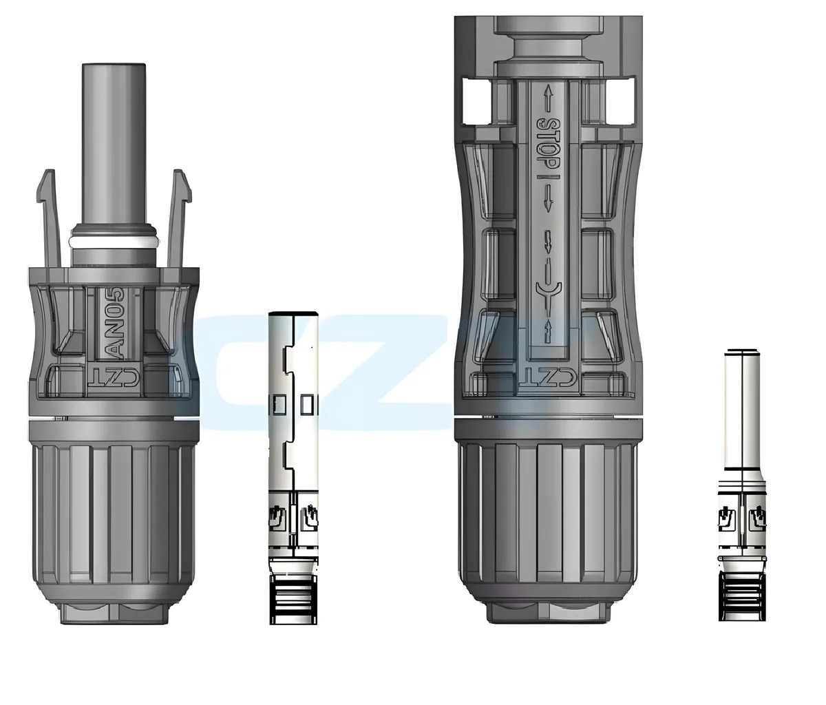
Figure 1. AN05 cable-end connector bodies and separate contact components in CZT's official product illustration. CZT source · Original image.
Control the instrument and sample condition
Use a measurement method appropriate to the required range and component test conditions. Record instrument identification, calibration status, measurement current and relevant timing. Choose test conditions from the approved procedure rather than assuming a higher current always produces a better measurement.
Record sample temperature and recent electrical loading. Resistance comparisons are more meaningful when the initial thermal condition is controlled. Preserve the same handling and connection method across samples.
Build the measurement sheet
| Field | Required record |
|---|---|
| Sample | Contact, housing, cable and batch identities |
| Boundary | Force and sense positions on a drawing |
| Instrument | Equipment, range and calibration reference |
| Conditions | Current, timing and temperature |
| Result | Raw values, repeats and relevant uncertainty |
| Sequence | Initial or post-exposure measurement |
Where an approved method uses additional techniques to address offsets, record them explicitly. Do not introduce an undocumented correction merely because a value looks unexpected.

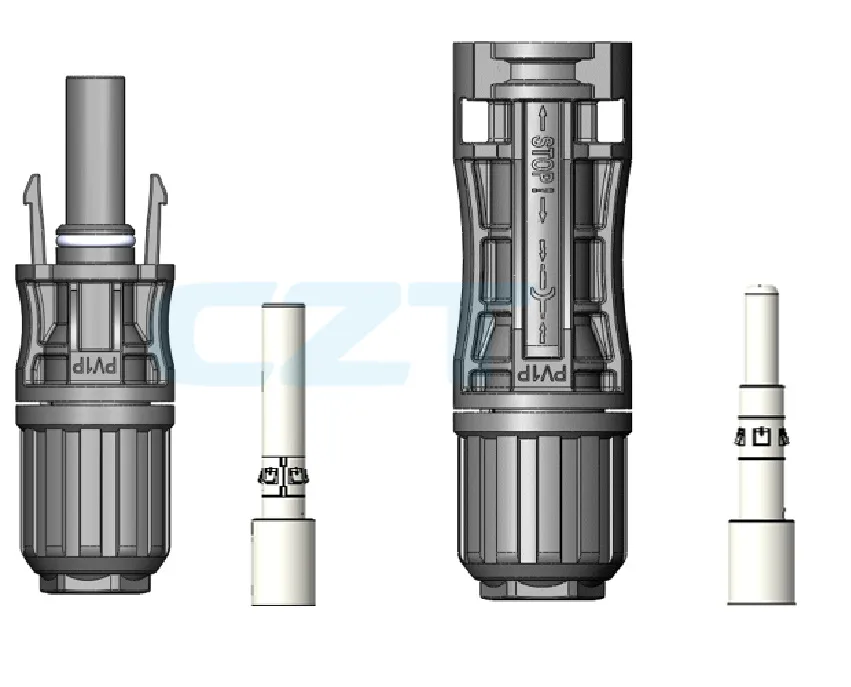
Figure 2. PV1P-A cable-end connector components in the official CZT catalog illustration. CZT source · Original image.
Investigate repeatability before comparing parts
Repeat the connection in a controlled manner and observe whether variation follows the sample or the attachment. Inspect sensing contacts and fixtures when a result changes with reattachment.
For a hypothetical comparison, one test could sense outside both crimps while another senses closer to the mating contacts. Their different values would not establish that one connector is better. The setups measured different electrical boundaries.
Use the result within a broader evaluation
Initial resistance and change after an agreed exposure answer different questions. Retain both values with their conditions rather than saving only a percentage change or final pass/fail label.
A resistance measurement can support process control and failure analysis, but it does not independently establish voltage suitability, sealing or full current capability. Keep those evaluations separate while using a common sample identity to connect the overall evidence.
Connect this review to CZT product information
Catalog references to discuss are listed below. Use the identifiers to request the current drawing and confirm the configuration required by your application.
| Catalog reference | Product information | Drawing record | Reference inquiry |
|---|---|---|---|
| PV cable-end connector, AN05 | PV cable-end connector, AN05 | Request the current drawing | Ask about this reference |
| PV cable-end connector, PV1P-A | PV cable-end connector, PV1P-A | Request the current drawing | Ask about this reference |
These entries identify catalog families. Their listing does not establish a numerical rating, finished-part tolerance or test approval; obtain that evidence for the requested revision.
Browse the relevant product family · View catalog resources
Discuss a drawing, sample or quotation
Share the part or family reference, current drawing revision, operating conditions and quantities. Include the specific checks described in this article so the inquiry identifies both the component and the evidence needed for your decision. Confirm sample availability and the proposed scope with the supplier.
Request a technical review or quotation
For broader context, read the related selection guide.