Review a PV connector's voltage suitability against the system's maximum relevant voltage, including the effect of low temperature on module open-circuit voltage. Selecting a connector from the array's usual operating voltage can leave the limiting condition unexamined.
The CZT solar PV family provides connector and junction-box references for an application review. The system calculation and the component's documented rating conditions must be evaluated separately before a particular model is approved.
Start with module data and site conditions
Identify the exact module, its open-circuit voltage reference value and the manufacturer's temperature-coefficient convention. Establish the project's required minimum design temperature using the applicable design method. A simulation default is not automatically the correct condition for a site.
Record how many modules are connected in series. Series voltage must be considered across the relevant interface, while other system components may impose additional limits. The responsible system designer should approve the calculation method and assumptions.

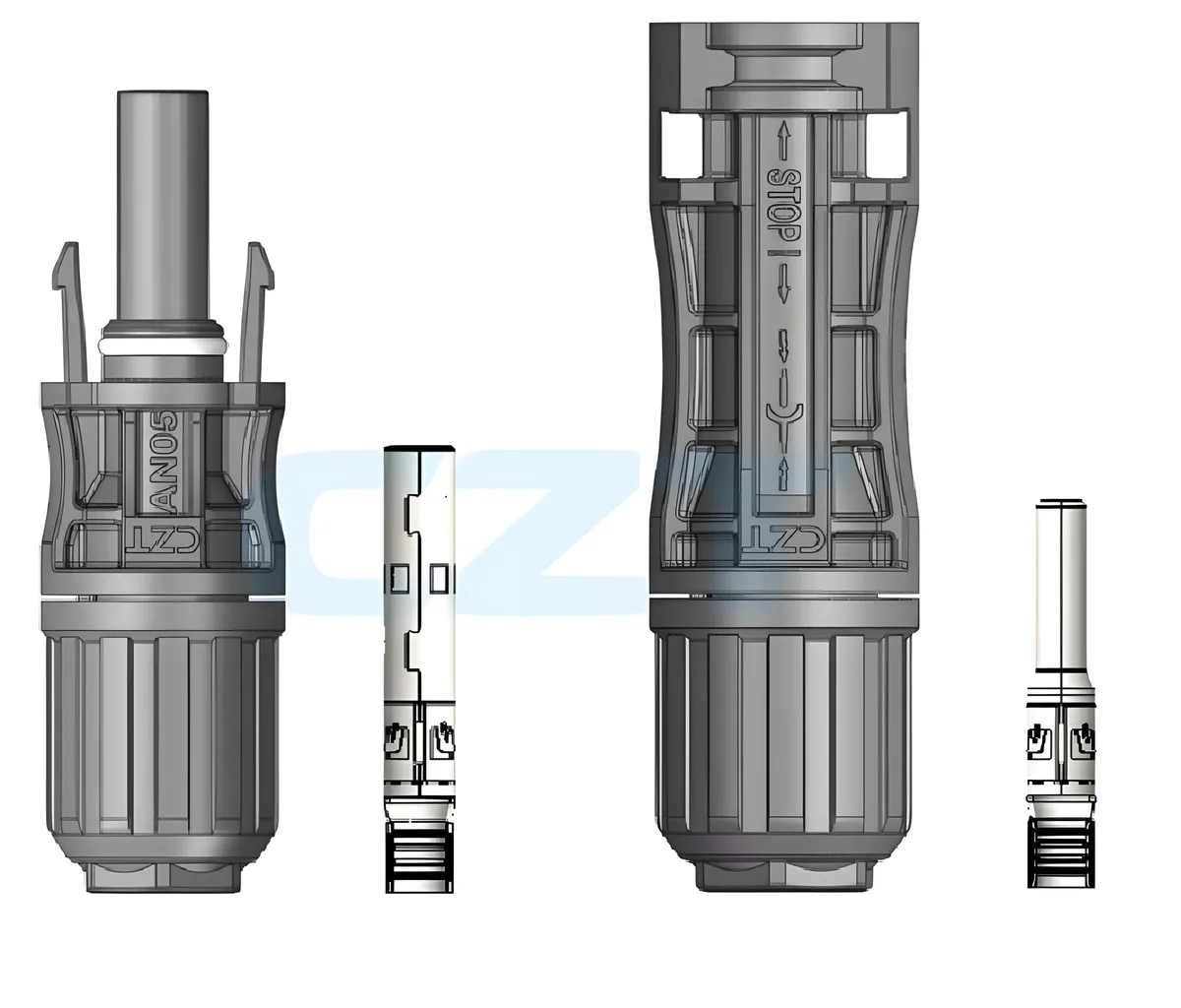
Figure 1. AN05 cable-end connector bodies and separate contact components in CZT's official product illustration. CZT source · Original image.
Work through a clearly hypothetical calculation
Suppose a hypothetical module has an open-circuit voltage of 50 V at 25°C and a relative voltage coefficient of −0.25% per degree Celsius. Using a simplified linear calculation at −15°C gives a 40-degree decrease from the reference temperature and a 10% voltage increase. The resulting illustrative module voltage is 55 V; twenty in series give 1,100 V.
These inputs are invented solely to demonstrate the calculation structure. They are not CZT ratings, a module recommendation or a complete project design. Actual module instructions, tolerances and required design factors control the real assessment.
Keep the review inputs visible
| Input or result | Evidence required |
|---|---|
| Module identity | Current manufacturer data sheet |
| Voltage and coefficient | Values, units and reference conditions |
| Temperature | Approved site-design basis |
| Series configuration | Released system design |
| Calculated maximum | Checked calculation and assumptions |
| Connector suitability | Exact model and applicable rating conditions |
Preserve the calculation version with the connector review so a later module or string-length change is not treated as electrically irrelevant.

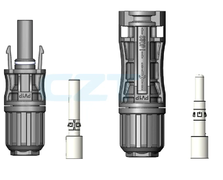
Figure 2. PV1P-A cable-end connector components in the official CZT catalog illustration. CZT source · Original image.
Compare the whole rating context
A voltage value alone does not establish every aspect of suitability. Review the intended application, insulation arrangement, environmental conditions and applicable documentation with the responsible engineer. Do not transfer a rating between connector variants or certification scopes without supporting evidence.
Also verify the actual paired configuration. A rating associated with one documented connector system should not be assumed to apply to an unreviewed mating combination.
Close changes through system review
If the module, series count or design temperature changes, repeat the relevant voltage assessment before reusing the previous component approval. This makes the decision traceable and prevents a purchasing description such as “PV connector” from concealing the actual electrical boundary the component must satisfy.
Connect this review to CZT product information
Catalog references to discuss are listed below. Use the identifiers to request the current drawing and confirm the configuration required by your application.
| Catalog reference | Product information | Drawing record | Reference inquiry |
|---|---|---|---|
| PV cable-end connector, AN05 | PV cable-end connector, AN05 | Request the current drawing | Ask about this reference |
| PV cable-end connector, PV1P-A | PV cable-end connector, PV1P-A | Request the current drawing | Ask about this reference |
These entries identify catalog families. Their listing does not establish a numerical rating, finished-part tolerance or test approval; obtain that evidence for the requested revision.
Browse the relevant product family · View catalog resources
Discuss a drawing, sample or quotation
Share the part or family reference, current drawing revision, operating conditions and quantities. Include the specific checks described in this article so the inquiry identifies both the component and the evidence needed for your decision. Confirm sample availability and the proposed scope with the supplier.
Request a technical review or quotation
For broader context, read the related selection guide.