A PV junction-box interface drawing should define everything between the box's internal termination and the external mating connector. Its purpose is to prevent different suppliers from making individually plausible parts that do not form the intended assembly. Control polarity, cable geometry, connector identity and acceptance responsibility on the same released interface record.
Mark the supply boundaries
Draw the physical assembly first, then mark where ownership changes. One supplier may deliver the box with installed leads; another may provide a cable assembly for final termination elsewhere. State who supplies each contact, seal and housing and who performs each termination.
CZT's solar PV connector family includes catalog references for cable-end connectors, panel-side connectors and junction boxes. BOX-1x and BOX-3x are useful identifiers for an initial discussion. They do not establish an internal circuit, lead configuration or compatibility with a particular cable-end part. Obtain those details for the actual purchased configuration.

Figure 1. BOX-1x assembly as illustrated on the official manufacturer product page. CZT source · Original image.
Define cable measurements unambiguously
Specify where the cable length begins and ends. A length measured from a housing face differs from one measured between electrical contact reference points. Include the intended free length, any stripped section and how the cable is routed during measurement.
Keep conductor identity, insulation color and circuit polarity as separate fields. Color supports identification but does not replace an electrical definition. Show a view orientation for pin or terminal labels so that a mating-face view cannot be confused with a cable-entry view.
Use an interface handover table
| Interface characteristic | Required drawing information | Acceptance owner |
|---|---|---|
| Internal termination | Terminal identity and termination process | Box assembly supplier |
| Cable segment | Cable identity and measurement datums | Cable assembly supplier |
| External mating end | Exact manufacturer and product pair | Design authority |
| Polarity | Circuit mapping and verification method | Final assembly quality |
| Revision | Drawing, BOM and change status | Document control |
Assign actual organizations and contacts before release. Leaving the ownership column blank often causes the final assembler to discover unresolved requirements after parts arrive.

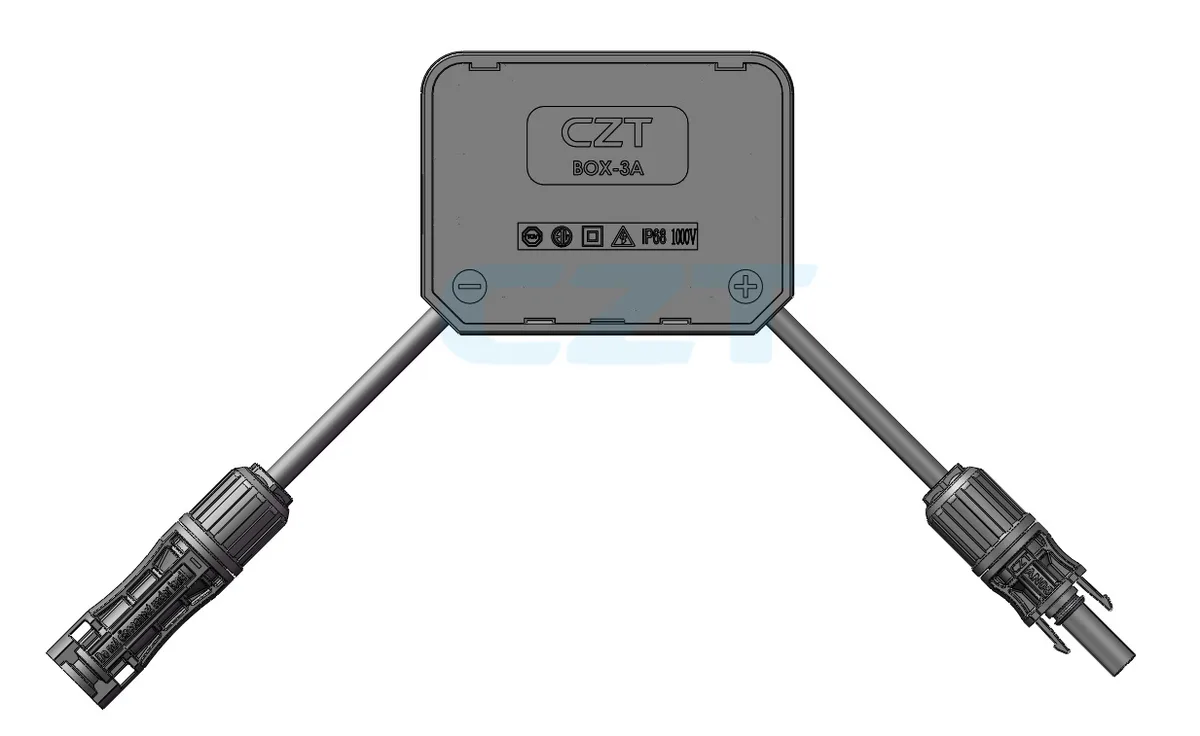
Figure 2. BOX-3x assembly as illustrated in the official CZT PV catalog. CZT source · Original image.
Verify the handover with samples
Inspect a first assembly against the drawing, including cable reach, routing and connector access. Perform the specified polarity and continuity checks before the unit enters the next production stage. Save the sample identification and inspection record with the drawing revision.
A practical failure mode is a lead that reaches its terminal in free space but pulls on the box after installation. Another is a connector whose polarity was described from the opposite viewing direction. Both can pass a superficial visual comparison while failing the intended integration.
The drawing package should therefore include an installed view and an explicit electrical map, not just a component photograph. When a box or cable supplier changes, repeat the relevant interface checks. A matching catalog name does not establish an unchanged assembly boundary or eliminate the need for first-article review.
Connect this review to CZT product information
Catalog references to discuss are listed below. Use the identifiers to request the current drawing and confirm the configuration required by your application.
| Catalog reference | Product information | Drawing record | Reference inquiry |
|---|---|---|---|
| PV BOX-1x catalog record | PV BOX-1x catalog record | Request the current drawing | Ask about this reference |
| PV BOX-3x catalog record | PV BOX-3x catalog record | Request the current drawing | Ask about this reference |
These entries identify catalog families. Their listing does not establish a numerical rating, finished-part tolerance or test approval; obtain that evidence for the requested revision.
Browse the relevant product family · View catalog resources
Discuss a drawing, sample or quotation
Share the part or family reference, current drawing revision, operating conditions and quantities. Include the specific checks described in this article so the inquiry identifies both the component and the evidence needed for your decision. Confirm sample availability and the proposed scope with the supplier.
Request a technical review or quotation
For broader context, read the related selection guide.