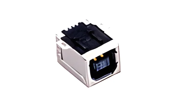
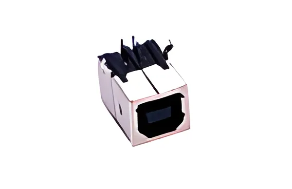
Choose a PCB USB 2.0 Type-B receptacle by its exact mating interface, board attachment and position relative to the enclosure. A familiar-looking opening is insufficient. The cable must reach full engagement while the board and shell anchors carry the expected handling loads.
For an initial search, the USB and HDMI connector family provides catalog starting points. Select the actual Type-B drawing before deciding whether a candidate fits. Standard-B, Mini-B and Micro-B are different mechanical interfaces; a product name containing B does not settle the question. The USB-IF USB 2.0 specification is the appropriate interface reference.
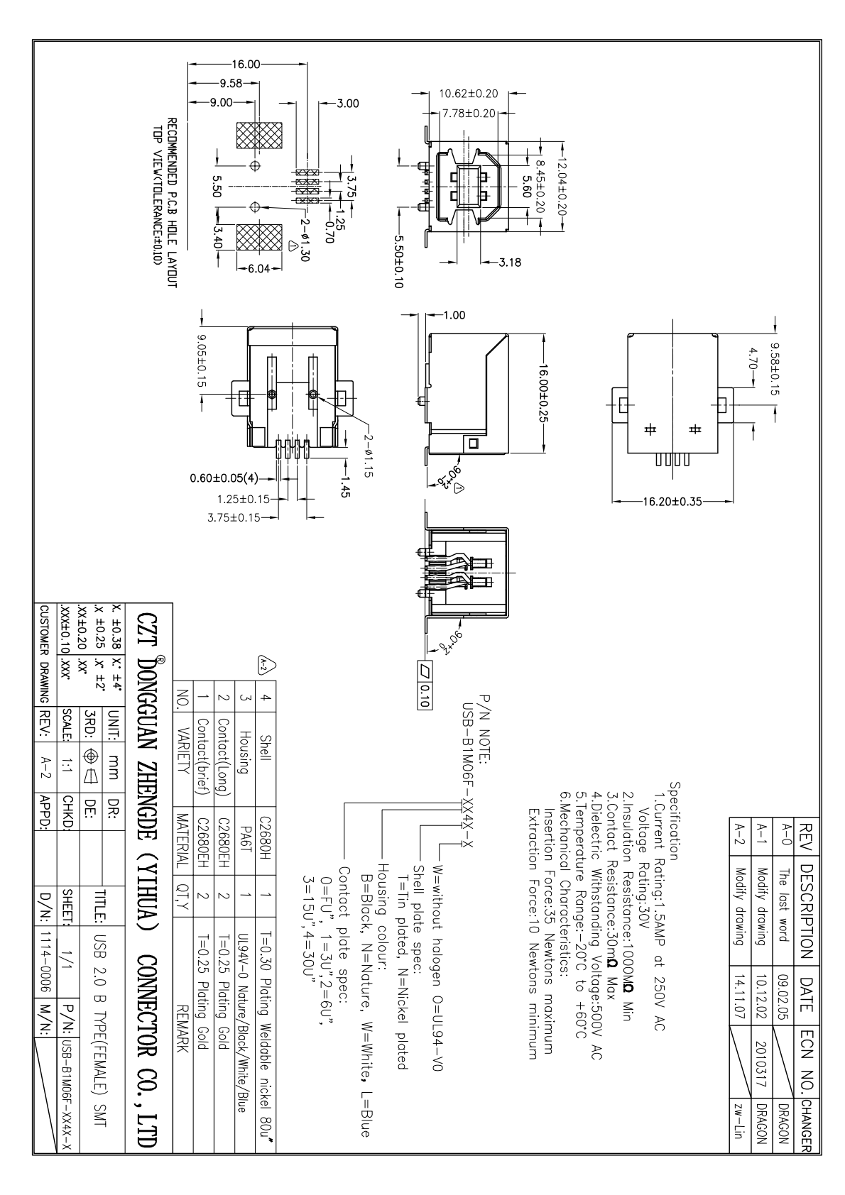
Figure 1. Official CZT USB 2.0 Type-B SMT drawing illustrates one board-mounting construction; compare orientation, seating and attachment with the intended PCB. CZT source · Original PDF, page 1.
Establish the insertion path
Start with the cable plug, including its overmold. Place its complete envelope in the enclosure model. Check the approach angle, finger access and clearance to nearby connectors. A panel opening that clears the metal shell can still obstruct the larger cable body.
Use the equipment mounting plane as a common reference. Record where the receptacle mouth sits relative to the outside panel surface. A deeply recessed connector may appear aligned in a rendering yet prevent the plug from reaching its intended seated position. Inspect that relationship with physical samples before freezing the enclosure.
Compare the board geometry
Determine whether the product requires a vertical or right-angle entry. Then compare terminal positions, board standoff, locating features and shell attachments against the controlled PCB footprint. Do not resize a similar library footprint without checking every feature.
| Review item | Evidence to record | Decision it supports |
|---|---|---|
| Mating mouth location | Dimension from PCB datum | Panel alignment |
| Signal tails | Pitch, row and land definition | Electrical footprint |
| Shell attachments | Hole or pad geometry | Mechanical load path |
| Body envelope | Maximum dimensions | Neighbor clearance |
Board thickness belongs in this review. A retention feature designed around one board construction may behave differently on another. Confirm the assembly method with the board supplier and connector drawing owner.
Check how handling loads enter the assembly
A cable creates loads beyond straight insertion. Consider sideways pulling, equipment repositioning and accidental pressure during maintenance. Trace those forces from the plug through the shell attachments into the PCB and its nearest supports.
For a hypothetical bench instrument, placing the nearest board support far behind the port could allow visible board flex during cable handling. Moving a support closer may improve the load path, but it remains a design proposal until checked on the actual assembly. More shell tabs alone do not establish a durability rating.
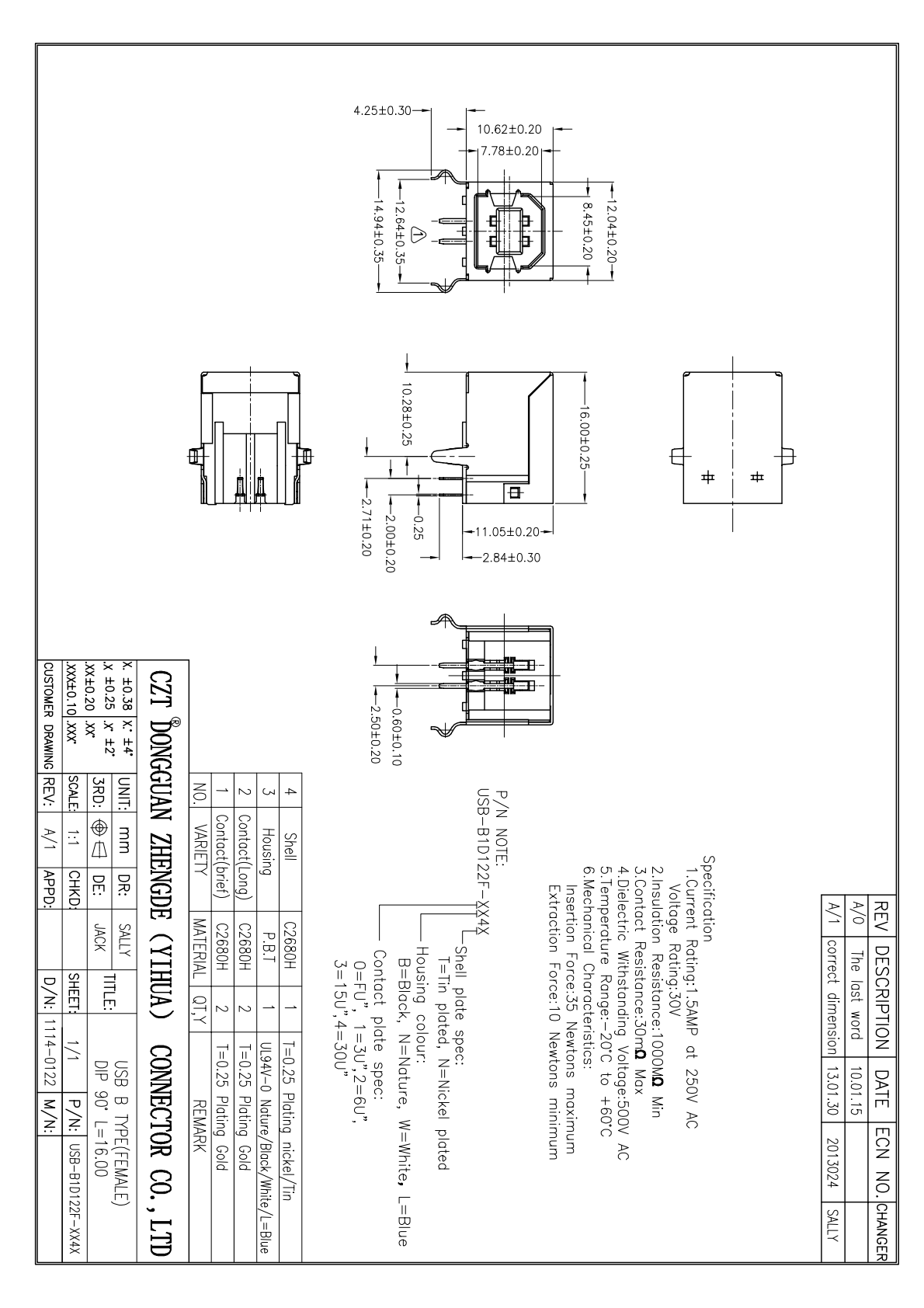
Figure 2. Official Type-B receptacle drawing provides orientation and mounting views for comparing the candidate with the actual board and enclosure. CZT source · Original PDF, page 1.
Close the selection with samples
Record the receptacle part number, drawing revision, mating cable and PCB version on the sample report. Check seating, accessible solder joints and communication before and after the agreed handling sequence. Photograph the panel gap and any board movement.
Approve the exact combination that was evaluated. If the cable overmold, panel thickness or board support later changes, revisit the affected checks. This keeps mechanical fit evidence tied to the product configuration that will actually ship.
Connect this review to CZT product information
Catalog references to discuss are listed below. Use the identifiers to request the current drawing and confirm the configuration required by your application.
| Catalog reference | Product information | Drawing record | Reference inquiry |
|---|---|---|---|
| 10308304xxxx | USB 2.0 Type-B female SMT connector, 10308304xxxx | Listed PDF | Ask about this reference |
| 10308204xxxx | USB Type-B female DIP right-angle connector, 10308204xxxx | Listed PDF | Ask about this reference |
A catalog drawing reference is a starting document, not a substitute for reviewing its revision, options and suitability for the complete assembly.
Browse the relevant product family · View catalog resources
Discuss a drawing, sample or quotation
Share the part or family reference, current drawing revision, operating conditions and quantities. Include the specific checks described in this article so the inquiry identifies both the component and the evidence needed for your decision. Confirm sample availability and the proposed scope with the supplier.
Request a technical review or quotation
For broader context, read the related selection guide.