HDMI connector signal validation needs a defined measurement boundary. A component fixture can characterize a local interface, while a complete equipment test includes the PCB, protection devices, cable and connected products. Neither result should be described as the other.
When reviewing catalog references in the USB and HDMI family, begin with the actual drawing and available characterization documents. A model name or familiar mating shape does not demonstrate a target data mode. The HDMI Licensing Administrator cable guidance also distinguishes cable categories and their intended capabilities; the cable identity belongs in a system evaluation.
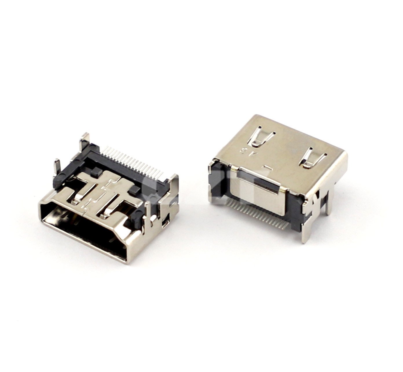
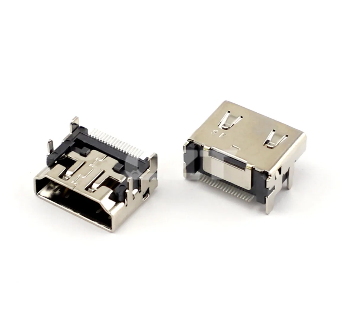
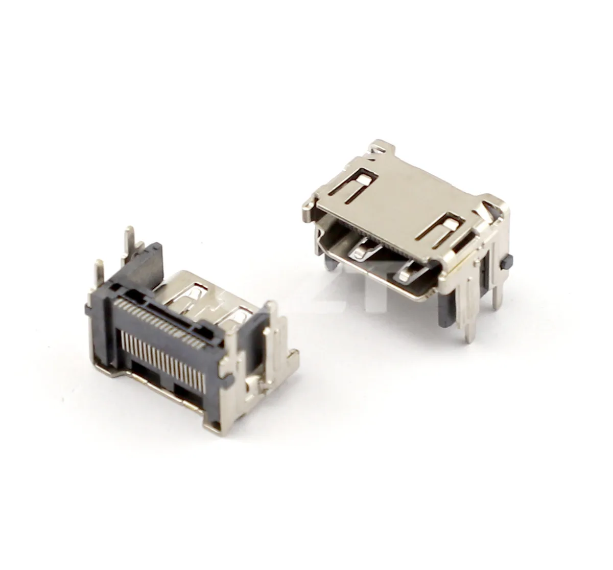
Figure 1. CZT HDMI receptacle photo identifies a component example for a signal-validation plan; appearance does not establish a supported transmission mode. CZT source · Original image.
Define what the product must support
List the intended operating modes and features, then identify the source, sink and cable combinations used to evaluate them. State the relevant implementation and test-document revisions. Avoid using a broad version label as a complete acceptance criterion.
Draw the channel from the transmitting device to the receiving device. Mark PCB traces, connectors, any switching or protection devices and the external cable. Identify which portions are included in each proposed measurement.
This channel diagram prevents a report measured on a short test coupon from being treated as evidence for a longer product route with different components.
Separate the evidence types
A fixture report is useful when its reference planes, calibration and sample geometry are documented. A system result is useful when its actual configuration and operating conditions are known. Keep both in the approval file with their respective boundaries.
| Evidence | Question it can address |
|---|---|
| Connector drawing | Interface and board geometry |
| Characterization fixture report | Performance within stated reference planes |
| Product-board evaluation | Behavior of the implemented route |
| End-to-end operating test | Behavior of the recorded source, cable and sink |
Do not invent missing limits or extrapolate a result to an operating mode that the setup never exercised. Ask the design owner or qualified laboratory to define the applicable criteria.
Control the comparisons
For a hypothetical connector alternative, test the old and proposed parts on equivalent boards with identified cables. Keep measurement methods and operating modes consistent. If the PCB footprint must change, record that the comparison includes a route change rather than attributing every difference to the receptacle.
Preserve raw measurements and setup photographs. A screenshot showing a passing image gives limited information about margin, repeatability or intermittent behavior. It should be accompanied by the checks specified in the product validation plan.
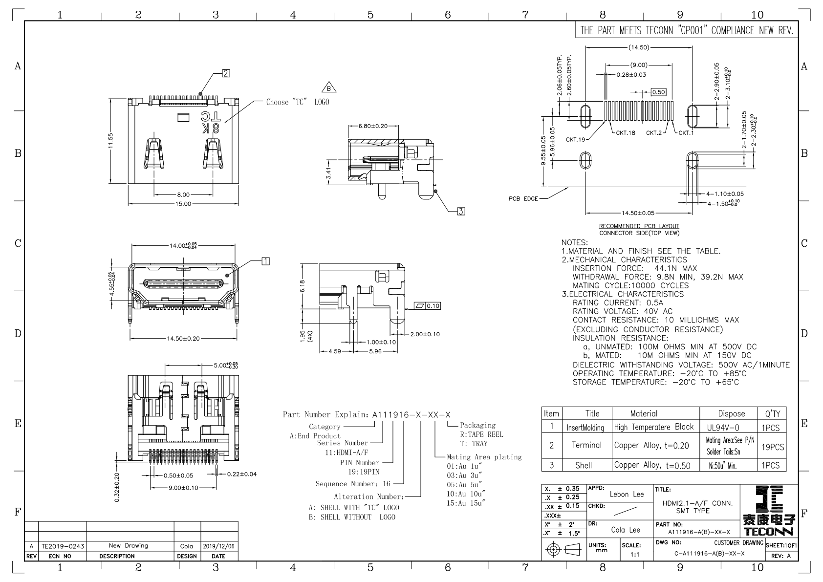
Figure 2. Official HDMI drawing defines physical component geometry, while high-speed evidence must identify the fixture, board path and tested operating conditions. CZT source · Original PDF, page 1.
Release an exact configuration
The approval record should identify component code, drawing revision, PCB route, assembly process and system configuration. State whether the evidence concerns engineering evaluation, formal compliance testing or both, using only the documentation actually obtained.
If purchasing proposes a nominally equivalent receptacle later, revisit the affected geometry and channel evidence. A shared HDMI mating interface is necessary for physical connection, but it does not remove the need to verify the implemented product channel and its required functions.
Connect this review to CZT product information
Catalog references to discuss are listed below. Use the identifiers to request the current drawing and confirm the configuration required by your application.
| Catalog reference | Product information | Drawing record | Reference inquiry |
|---|---|---|---|
| A111916 | HDMI Type-A receptacle, A111916 | Listed PDF | Ask about this reference |
| A111918 | HDMI Type-A receptacle, A111918 | Listed PDF | Ask about this reference |
A catalog drawing reference is a starting document, not a substitute for reviewing its revision, options and suitability for the complete assembly.
Browse the relevant product family · View catalog resources
Discuss a drawing, sample or quotation
Share the part or family reference, current drawing revision, operating conditions and quantities. Include the specific checks described in this article so the inquiry identifies both the component and the evidence needed for your decision. Confirm sample availability and the proposed scope with the supplier.
Request a technical review or quotation
For broader context, read the related selection guide.